Voice Controlled Lamp
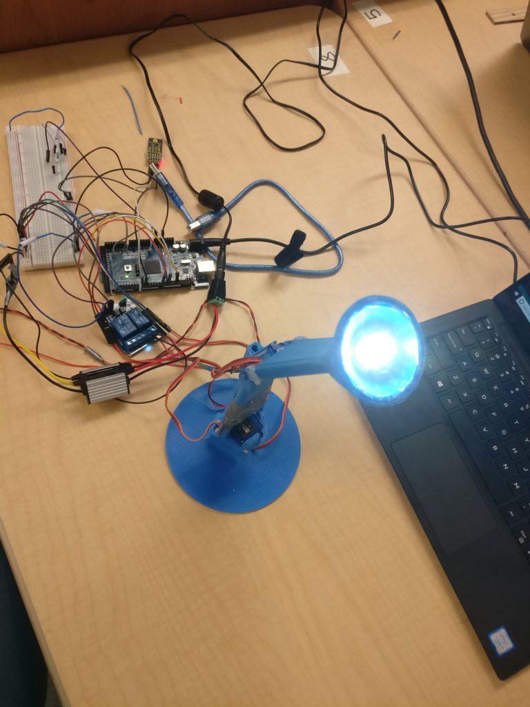
This lamp turns on/off and rotates, tilts, elevates, and falls a certain number of degrees from a voice command.
Engineer
Zachary W.
Area of Interest
Computer Science
School
Homestead High School
Grade
Incoming Junior
Reflection
After selecting the voice-controlled lamp, I initially planned on finishing this seemingly easy project in around a week. Little did I know, the project would not only take me the entire time allotted to make the project, but also take me through ups and downs along the way. Constant, albeit simple, mistakes and roadblocks from my lack of prior knowledge of electrical components prevented me from traversing through the project at the speed I would like to be at. Although all of this makes it sound like my few weeks here were extremely pedestrian, choosing to join this program and making the lamp was definitely not a mistake. The program opened my eyes to the vast world of engineering and circuits, shining light on something I probably wouldn’t approach at home. After this, I plan on creating more projects that involve circuitry, as these few weeks have shown me that mechanical and electrical engineering can be a blast.
Final Milestone
Final Milestone Images
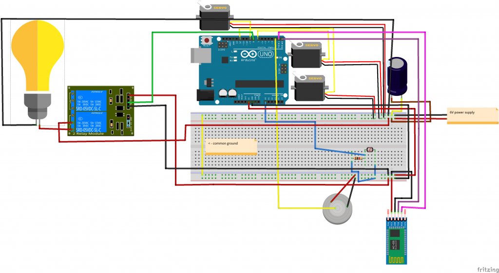
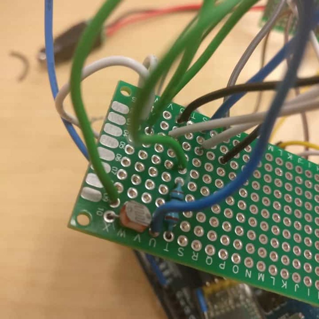
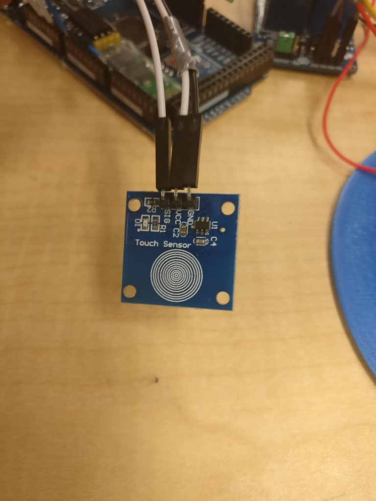
For my final milestone, I added a photoresistor and a touch sensor to my circuit. I also swapped my breadboard for printed circuit boards.
A photoresistor is a variable resistor that changes its resistance based on the intensity of light in the environment. For example, if the photoresistor was in a bright room, the resistance would be very low, but if it was in the dark, the resistance would be extremely high. I can measure the voltage drop across this photoresistor, which the Arduino then reads. I can use this value to decide whether to turn on or off the LED.
A touch sensor is similar to a button, but no pushing is involved. When you touch the sensor plate, the plate and you form a capacitor. The Arduino then measures how much time it takes for plate-you capacitor to charge, which it then uses to estimate the capacitance. I use this sensor to turn my lamp on and off.
The largest problem I had was about my photoresistor’s circuit. The values my Arduino was reading were extremely small. I discovered that the resistor I used for the voltage divider was too big, so there wasn’t much of a voltage drop, due to the voltage divider rule. By changing my resistor from 10k Ohms to 1k Ohms, I could more accurately turn on and off my lamp.
My finished code is named lamp on my github.
Third Milestone
Third Milestone Images
My third milestone is finishing the code for the other two servos and building the lamp.
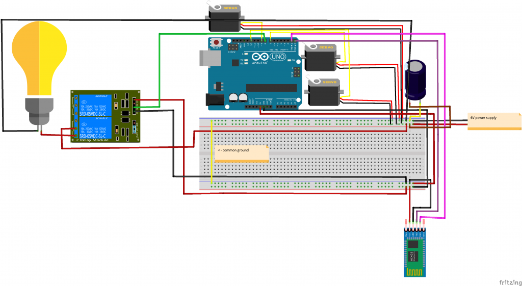
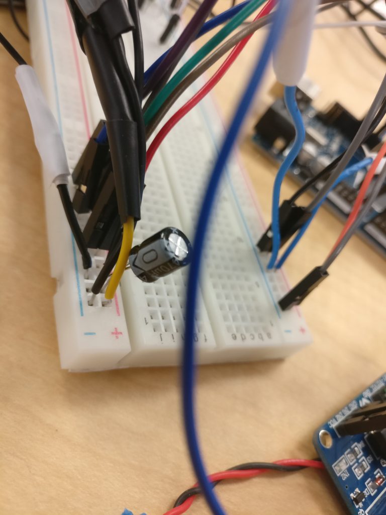
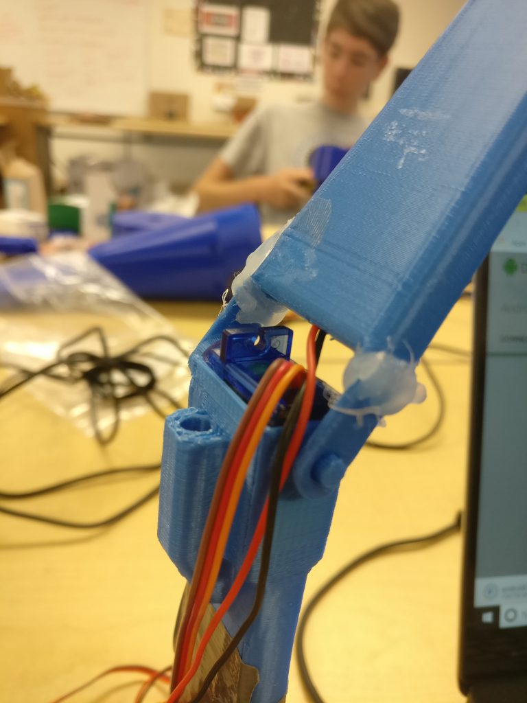
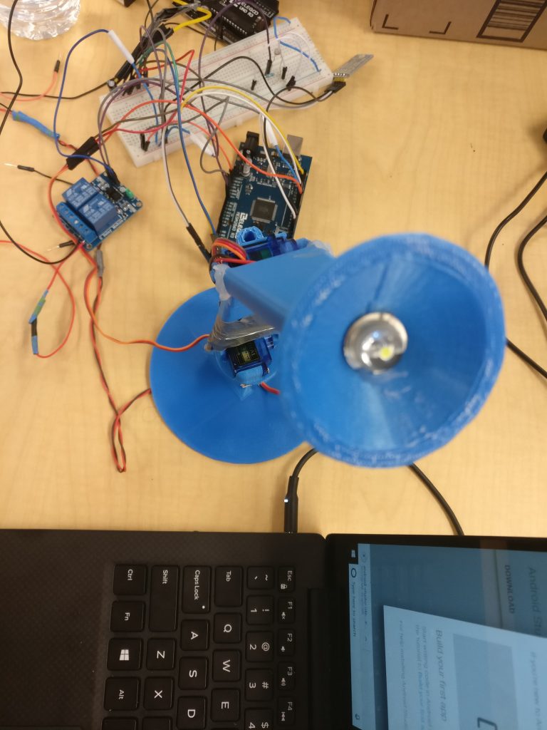
In this milestone, I added a capacitor, a common ground, a new way of moving servos, and some more commands for the lamp. For the servos, I move them using for loops now, one degree at a time, with a delay between each degree. This way, the servos move much slower, so there is a smaller chance of the lamp breaking. Some commands I added were down, up, and lumos (Harry Potter spell!).
Although setting up the lamp and coding the other two servos should be relatively simple, I encountered many challenges in the process. My first challenge had to do with the servos buzzing. The servos wouldn’t move, and would start to buzz louder and louder. What solved this was putting a capacitor and a common ground in my circuit. I needed a capacitor because the servos were drawing spikes in the current, so the capacitor was there to stabilize the voltage. The common ground is an imperative part of the circuit as voltage is only relative, and needs to be compared to a zero level or ground.
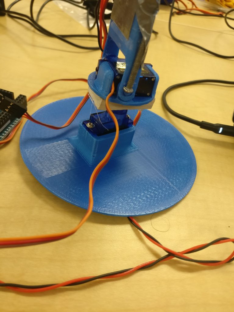
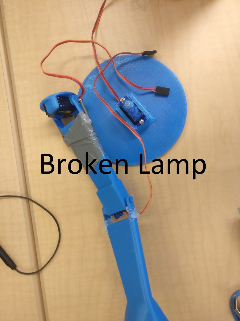
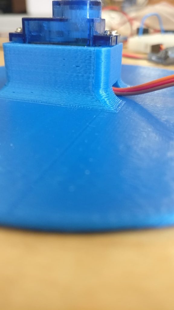
Another problem was with the 3d printed materials. While I was testing, the part connecting the base servo and the rest of the lamp snapped, so the bottom servo was rendered useless. I had to rebuild another lamp, meaning that I had to wait for materials, or think of a better idea. What I eventually did was replace the old servo, add a servo horn to the new one, and glue it along with a wooden block to the rest of the lamp. I also wanted to make sure that the same thing doesn’t happen again. I had a few options: build a support for the part, or to use the middle arm less. I decided to do the latter due to a lack of time. I also tried to make sure that the lamp always kept its center of mass in the same place. I did this by moving the middle arm by one degree every five degrees the top arm moves.
My code for this milestone will be on my github.
Second Milestone
Second Milestone Images
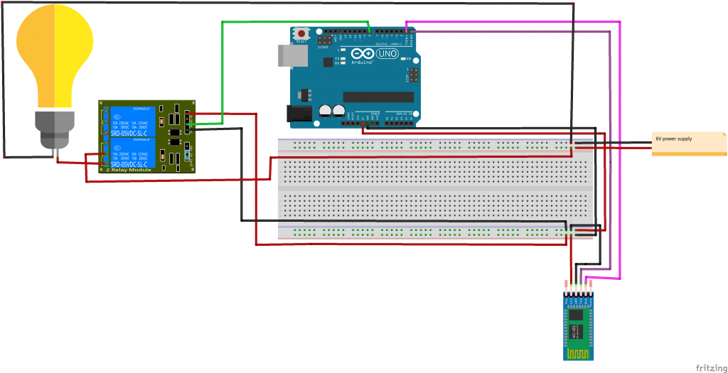
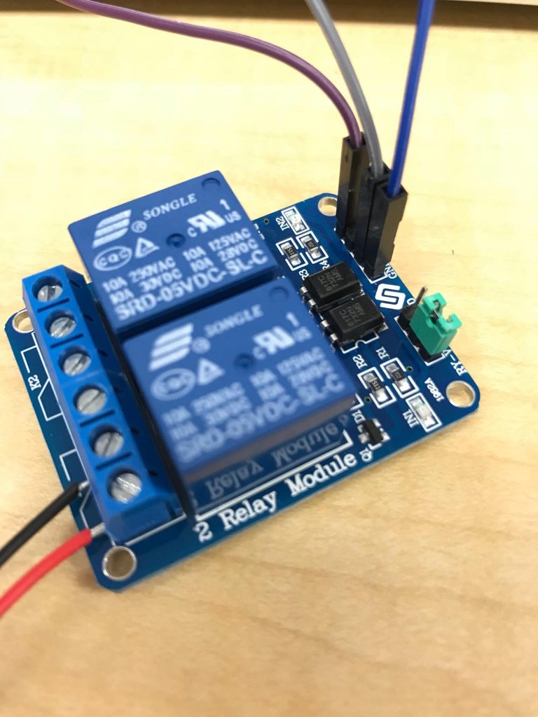
My second milestone is controlling the LED with a relay using my voice.
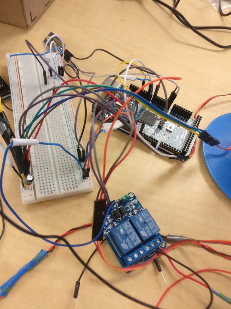
A relay is an electromagnetic switch that can control the flow of current. There are usually three input pins on a single channel relay: VCC (power), IN (input), and GND (ground). For output pins, there are NC (normally connected), NO (normally open), and COM (common). A relay is activated when the input voltage is under 2V. When activated, the electromagnet in the relay creates an electric field, the armature, a lever of some sort, is moved so that it changes the contact of COM from NC to NO. When the electromagnet’s current is cut off, the armature falls back to it’s original position, so COM is connected to NC.
My code remains similar to the last milestone, but instead of rotating the servo whenever the condition is met, I control if the relay lets current through or not. My code is located on my github.
The main challenge I had was both researching about the relay, and also figuring a way to build my circuit. The part that confused the me most was planning out the part of the circuit involving the power source, the relay, and the LED. Eventually, I realized that the current should travel to the common, through whichever electrical contact I choose, and through the LED.
First Milestone
First Milestone Images
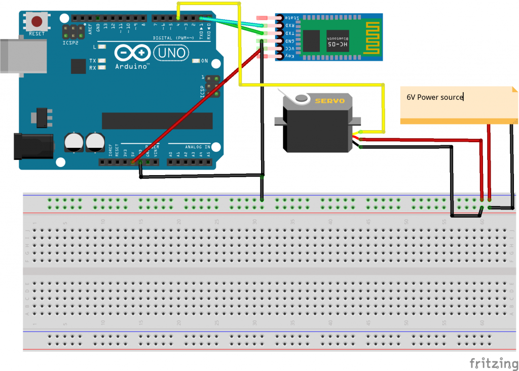
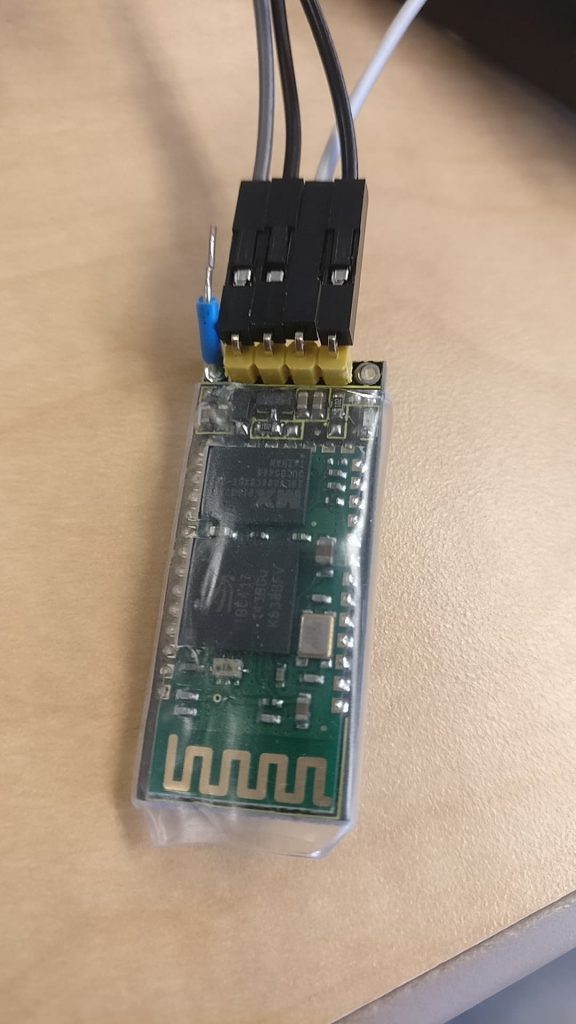
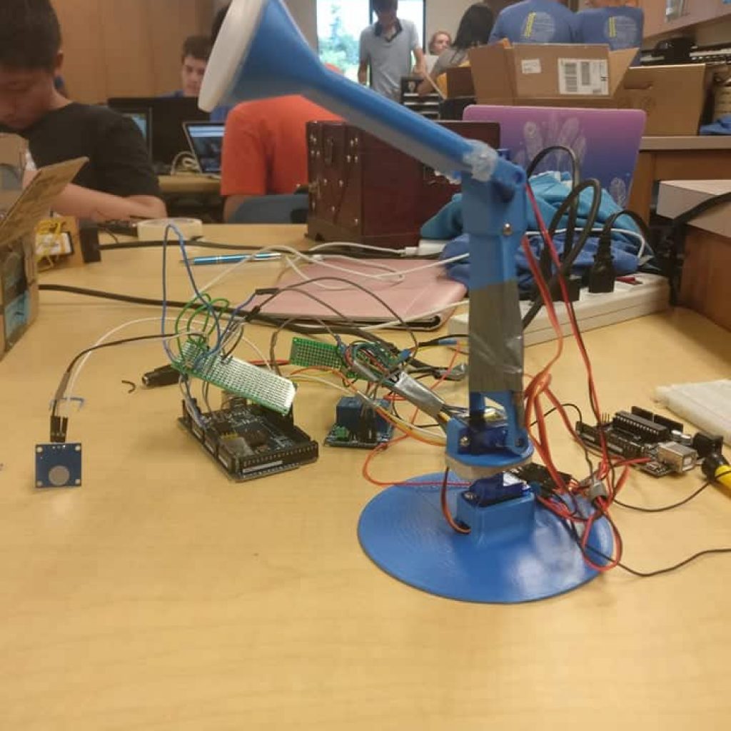
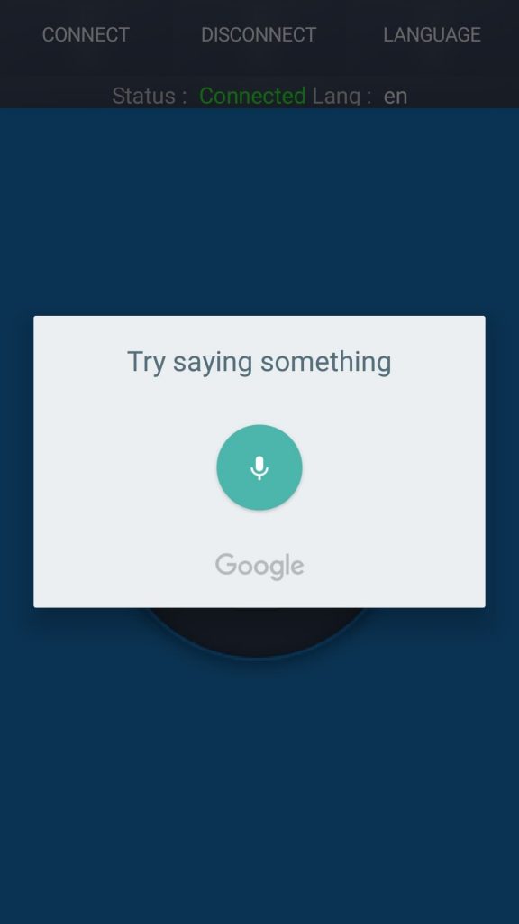
My intensive project is a voice-controlled lamp that is controlled by speaking into a smartphone. The smartphone relays the command to the Arduino, through a bluetooth module. The Arduino then commands the servos to rotate/tilt a certain number of degrees in a certain direction, or the light to turn on and off. This way, you don’t have to put aside what you are currently doing to turn on/off a light or move it; a voice command does the job. Although voice recognition isn’t perfect, it introduces a whole new level of convenience. My first milestone is just the rotating base of the lamp, that can be controlled with my voice.
I first worked on getting the servos to rotate when connected to the Arduino. Afterwards, I worked on connecting the bluetooth module to the Arduino. I tested the bluetooth module through sending a 1 or a 0 from my phone to the Arduino, which turns on or off a LED. Afterwards, I tested the bluetooth module with voice commands. I said either on or off to turn off a LED. Once I was sure that I was able to order the LED with my voice, I moved onto the base servo, which I attached to the 3d printed base of the lamp. My code for each one of these were all relatively similar. I read what came from the bluetooth module, and then if what was read matched the conditions, I would turn on/off a LED or move the servo.
I faced a lot of roadblocks in the process of completing my first milestone. The largest one was learning about everything I was doing. I had to learn about what each one of the color coded cables of the servo did, how the breadboard is wired, and also how to build a circuit. An extremely time consuming roadblock had to do with the bluetooth module. I wasn’t able to export my code to the Arduino, and after a lot of googling, I was told that you had to leave the 0 pin unused when exporting, which solved my problem.
My code for my first milestone is on my github.
I got my 3D printed materials from here.
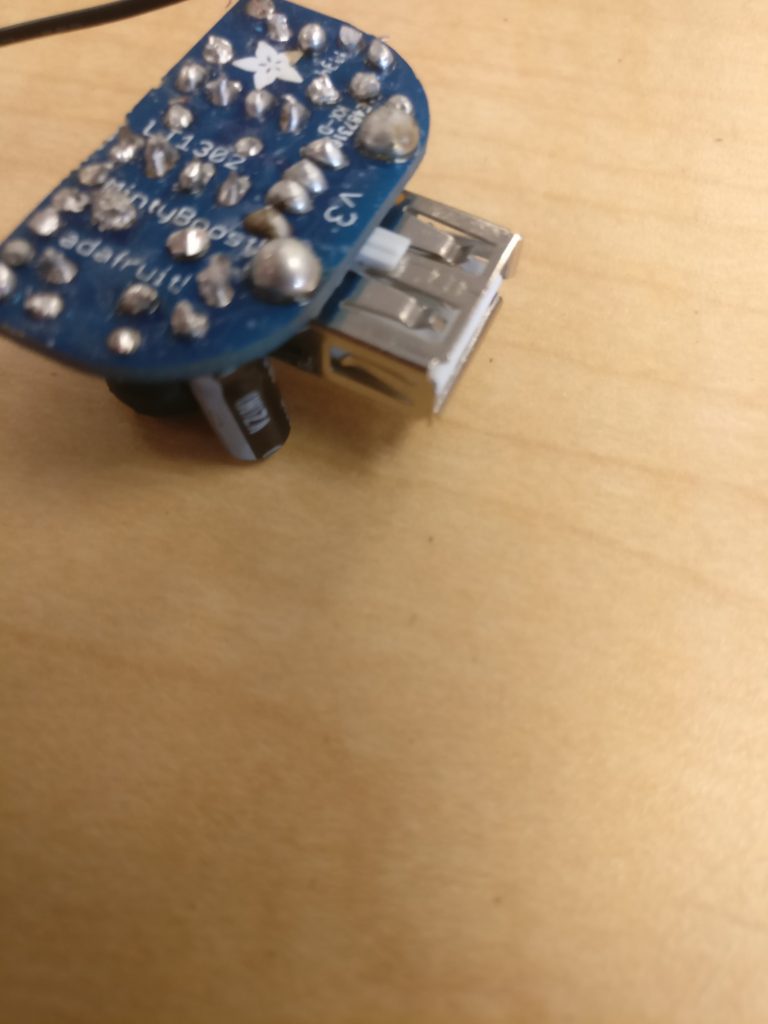
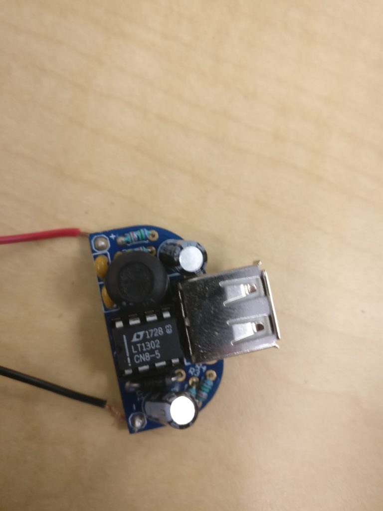
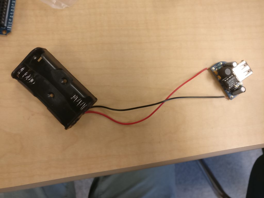
Starter Project
Starter Project Images