
Hi, my name is Zac, and I’m a rising sophomore at Hunter College High School. For my project, I built an RC tank. It is controlled by a wireless PS2 controller, and is programmed by an Arduino board and a motor shield. The tank also has an ultrasonic sensor on the front and a shovel controlled by servo motors in the back.
I had a blast here at Bluestamp Engineering. I love how the freedom I was given: I was able to do whatever I wanted with my project, in whatever way I wished. I could use whatever materials I wanted and was always able to get new materials. I actually liked the fact that the instructors almost forced you to figure issues out yourself, as it gave a good challenge. I learned a lot about Arduino and programming. This camp was the first experience I had with programming, and I learned a lot about the language and the concept of coding. I had fun figuring everything out myself, and I hope to continue to do this as I grow up. I enjoy this, and I hope that I will continue to do this throughout my life.
RC Tank

Final Milestone
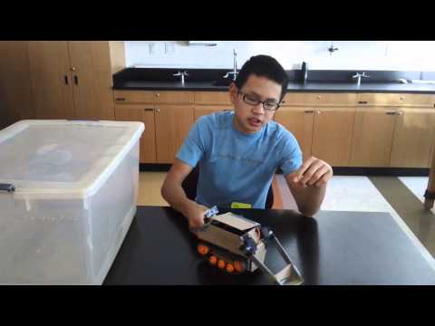
The modifications I added on to my tank were an ultrasonic sensor and a shovel in the back controlled by two servo motors. The ultrasonic sensor was attached to the tank through a hole in the outer cardboard layer. I attached the ultrasonic sensor into a hole in the cardboard. The sensor is coded so that anytime it sense something closed than 25cm to the sensor, the tank will turn right until there is nothing in front of it. I coded the controller so that when I hold down a certain button, the sensor will turn on. The tank will drive forward until the sensor detects something, and then it will turn. Next, I added the servos. When I press the up button on the controller, the servos will lift the shovel upwards. When I press the down button, the servos will lower the shovel. Then I added a simple cardboard cover to the outside and tops on the tank. It is powered by a portable iPhone charger through a jumper cable.
Documentation
Here is the code I used for my tank:
Here is my build plan and the bill of materials needed for my project (note that all materials for the modifications are not on the bill of materials):
https://docs.google.com/spreadsheets/d/1WBGCo28kl7JIsup5pi5lmpp6Vu1-BxHKziw1LDjSycc/edit#gid=0
https://docs.google.com/document/d/1_kIvFBqj3KxVvh8ArtsnzR_JAEWiqM3jCptSfueUq_A/edit
Modifications
The modifications I added on to my tank were an ultrasonic sensor and a shovel in the back controlled by two servo motors. The ultrasonic sensor was attached to the tank through a hole in the outer cardboard layer. I attached the ultrasonic sensor into a hole in the cardboard. The sensor is coded so that anytime it sense something closed than 25cm to the sensor, the tank will turn right until there is nothing in front of it. I coded the controller so that when I hold down a certain button, the sensor will turn on. The tank will drive forward until the sensor detects something, and then it will turn. Next, I added the servos. When I press the up button on the controller, the servos will lift the shovel upwards. When I press the down button, the servos will lower the shovel. Then I added a simple cardboard cover to the outside and tops on the tank. It is powered by a portable iPhone charger through a jumper cable.
3rd Milestone
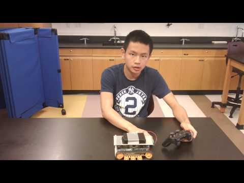
For my third milestone, I wanted to have finished building my tank. This means assembling the mechanical parts of the tank, coding the arduino to run the motors, and then coding the arduino to respond to the PS2 controller. The mechanical assembly and the coding for the motors had been finished in milestones 1 and 2, so for milestone 3 I had to code for control from the PS2 controller. First, I downloaded the ps2x library and ran the PS2 controller test. In this test, the computer would print certain phrases each time a button was pressed. The test worked, and then I began to code for motor control from the PS2 controller. To write this code, I used the DC Motor test code I had used in milestone 2 and the PS2 controller test code and combined the two. I used their codes for the libraries and setups. I coded the arduino so that pressing L2, L1, R2, and R1 buttons would control the motors. However, when I first uploaded the code to the arduino I had issues. When the arduino was being powered by a battery instead of the computer, I would press one of the buttons, and the motor and treads would begin to turn. However, they would turn at an extremely fast rate and wouldn’t stop. I tried switching from a 9 volt battery to a battery case of 6 AA batteries, but the problem continued. However, I noticed that when the motors were turning and not stopping, the receiver for the PS2 controller would lose power. This made me think that 9 volts isn’t enough power to power the motor and receiver. To fix this, I lowered the speed of the motors, so they wouldn’t need as much battery and the receivers could get power. When I tested this, everything worked: the motors would run as long as the button was pressed, but would stop when the button was released. The PS2 controller had full control of the motors through the arduino.
Next, I had to place the arduino, wires, and battery case onto the tank body. I screwed on some nylon standoffs to support the arduino. I attached the receiver to the motor shield, and then soldered the wires onto the motors. Next, I had to put the battery case onto the tank. I couldn’t put the case at one end of the tank, because it is too heavy and would tilt the tank. I had to assemble a stand using cardboard and nylon standoffs, and create a second platform above the other parts of my tank. I then duct taped the battery case onto the raised platform. Finally, to clean up the pieces of my tank, I ziptied all of the wires together and taped the receiver onto the bottom of the raised platform.
2nd Milestone
For my second milestone, I wanted to have programmed the Arduino board and the Adafruit motor shield to help run the motors and treads. First, I ran the blinking LED test on the Arduino board to test the board and learn about Arduino programming. After, I had to solder the Arduino Uno board and the motor shield together. Then, to test the motor shield, I ran the DC Motor test. This showed that the motor shield works. Next, I wanted to program the board and shield to run two motors at once. First, I attempted to use the code on the website that provides instructions for building the tank. However, there was an error in this code: the code used the wrong digital pins, so it could only run one motor at a time. I couldn’t find what the correct pin was, so I couldn’t use that code. Because of that, I had to find a new code to power both motors. I found a possible code on the website I got the motor shield from. I tried to apply it to my tank, but I ran into a series of issues. First, I had trouble with new functions. Functions are series of code that are put under a single common, unique name that codes for a specific task. The code had a series of functions that weren’t in the preprogrammed libraries. I had to find which libraries each was in, and then include and declare each library and function into the Arduino. After that, I ran into a large number of problems. First, I had difficulty finding which library many of the new functions were in. There were many new functions and new libraries I had to examine to attempt to find which function belongs in each library. Sometimes, they were libraries inside other libraries, or functions that are from libraries I haven’t even downloaded yet. It was too much work to find each library and fix the code. In the end, I decided to adapt the DC Motor Test, which I had successfully used previously, and have the code run for 2 motors. I added another motor into the coding, and had it do the same exact actions as the first motor. After uploading that to the Arduino, both motors worked.
1st Milestone
For my first milestone, I wanted to have assembled the mechanical parts of the tank. This means assembling the chassis, treads, wheels, and motors, and putting everything together. First, I used a Tamiya Universal Plate Set as the body of the tank. I screwed in some accessories to help attach the wheels. I put 3 sets of small wheels on the bottom of the plate in the middle to act as runners. Then, I added 1 set of large wheels at the front on top of the plate. After, I assembled the motor. I had to assemble the gears and the casing for the two-part motor. I decided to make the motor have a gear ratio of 114.7 : 1, which would mean a 115 rpm speed for the motor. The gear ratio is the ratio of the angular velocities of two connected different sized gears, and it can be directly calculated from the number of teeth on each gear. Then I attached the motors to the top of the back end of the universal plate. I added a set of motor wheels to the motor, so they could help move the tread. Then I had to make the treads to place on the wheels. I made the treads each have 58 links. After that, I had assembled the tank. Next, I wanted to test the tank and make sure it works. I got a 3 volt AA battery case to test. I only had the wires touch the motors, to make sure that motors will turn and cause the treads and wheels to move. I tested both motors, and both worked fine: the treads spun as soon as the wires touched the motor.
The first time I tested the motors, it didn’t work. The motors would spin, but the gears inside the motor wouldn’t catch and the treads would spin. I had to disassemble the entire motor and detach it from the chassis. I found that I hadn’t placed one of the gears correctly inside of the motor. This small mistake caused the entire motor to not be able to function. I had to fix the gear, reassemble the motor and attach it to the chassis. After I had fixed that issue, the motor worked perfectly, and the treads spun.
Starter Project
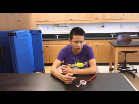
My starter project is a watch that I assembled myself. It has a 4 digit, 7 segment LED display that will show the time. It is triggered by a button on the side. Pressing it once will display the time, pressing it a second time will turn off the LEDs. If you hold the button, the numbers will increase and you can change the time on the watch. The watch is powered by a CR2032 coin cell battery. There is a 10k ohm resistor to prevent too much electricity from flowing to the LEDs so the diode won’t burn up. The preprogrammed ATmega328 microcontroller controls the watch and helps it run properly. There are two 0.1uF capacitors that help store energy, as well as a 32kHz crystal that helps the watch find and keep the correct time. The watch is enclosed in a clear acrylic casing that helps protect the watch. There is then a strap that weaves through the acrylic casing to strap the watch to your wrist.
The biggest thing I took away from this project is how to solder. I had to solder many different pieces into the circuit board, and it gave me plenty of practice with soldering. The hardest part of this project was the precision and attention to detail. I had difficulty with the small parts, and the precision with which the parts needed to be placed.