

Hi, my name is Yuki W, and I am a rising junior at San Domenico School. In the past two years, I participated in my school’s robotics club as a mechanic and a programmer. However, most of the things that we did were simple, and I never learned about circuits or the Arduino. BlueStamp Engineering allowed me to experience the struggle and the satisfaction of being an engineer. It introduced me to an innovating, exciting world that is full of opportunities.
In BlueStamp Engineering, I faced a lot of challenges and frustrations that took days to solve. My biggest challenge overall was how to make the LCD display the questions and check the answers that were stored in the SD card. In the beginning, the Arduino could only read the text and display it as a string on the Serial Monitor. When the Arduino tried to display the question on the LCD, it could only print out random symbols. With help from my instructors, we modified my code so that the Arduino would read letter by letter and store that information in an array. I enjoyed the satisfaction and relief when I finally solved a difficult issue. I was really glad that I was able to complete my self-defined project, which had a limited amount of documentation.
After spending six weeks at BlueStamp and listening to speakers about their passion and motivation, I was inspired to continue working on more projects on my own. Currently, I want to work with Arduino Lilypad, which is a wearable micro-controller, and create a voice recognition device that will manage my to-do list. I am also considering building a display at my house to project my to-do list and write a program on my computer that will automatically take note of homework deadlines from my school’s website.
BlueStamp Engineering increased my confidence and allowed me to create new projects and approach issues like a real engineer.


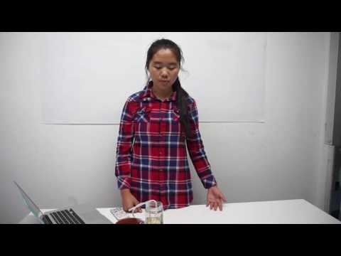
My main project was a self-defined project: Smart Plant Manager. I decided to work on this project because I wanted to build a device that would take care of plants as well as educate people about plants and environmental issues.
Now the Smart Plant Manager can display a menu that consists of “Plant’s Status”, “User Point”, “Quiz” and “Blynk”. In “Plant’s Status”, LCD can display the humidity in soil, the temperature in Celsius and Fahrenheit, and the water level in the water container. When the humidity is low and there is at least one user point, the water pump will automatically run to water the plants. User points can be collected by answering questions correctly in the quiz. There are 20 questions about plants and environmental issues stored in the Arduino’s SD card. The Arduino will generate a random number each time to decide which question to display.
Arduino now can also communicate with BLYNK to display all the sensors’ datas. When the water level in the container for the pump is low, BLYNK can send me an email to remind me to add more water to the container.
![]() Yuki Wang’s BOM and Build Plan
Yuki Wang’s BOM and Build Plan

For my final video, the Arduino can send all the sensors’ values to an app called BLYNK by connecting to a computer. I changed from an Arduino Uno to an Arduino Mega so that there would be enough flash memory to store my sketch.
In the beginning, I tried to make the Arduino create a web server that will display all the sensor value. However, the wifi shield CC3000 suddenly stopped working and would not be able to get any data from its server. I then tried to connect my Arduino to BLYNK by using its example code. Nevertheless, the wifi shield had the same issue like the web server. I looked up on numerous forums about this problem, and most of them recommended me to upgrade the firmware of the shield to 1.13 or 1.14. Although I ran the program repeatedly, the wifi shield would never get past initialization.
Therefore, I decided to connect my Arduino to my computer and then connected it to Blynk. The challenge that I faced during the process was that the documentation on Blynk’s website was not clear about how the run the program on my Mac. I searched for other tutorials and watched videos of people demonstrating how to connect Arduino to Blynk through a USB port. Eventually, I figured out that I needed to first install BREW then SOCAT on terminal before running the file, which allowed Arduino to use my Mac to send data to BLYNK. When I started the program, I needed to first type out “chmod +x” and the file path of “Blynk-ser.sh”. (The entire command looks like this: chmod +x /Users/LunaY_Yuki/Documents/Arduino/libraries/Blynk/scripts/blynk-ser.sh) This command gave me permission to open the file. Then I needed to type “sudo” and the file path again. (The entire command looks like this: sudo /Users/LunaY_Yuki/Documents/Arduino/libraries/Blynk/scripts/blynk-ser.sh) This command opened and ran the file. The terminal would prompt me to enter the password for my computer and then asked me to type the port (it was displayed on the top of the serial monitor) that the Arduino used to connect my computer.

 In order to start the connection with Blynk, I added another menu item called “Blynk”. The Arduino would establish a connection when I selected “Blynk”. Because Blynk used the USB port to contact the Arduino, my serial port needed to be close when I was using the app. If I wanted to quit the app and continued to use other function, I needed to press CTRL+C on my terminal and restart my Arduino.
Because my Arduino calculated the analog reading of the temperature sensor and then displayed the correct value, I modified my code so that the Arduino could send the calculated data to Blynk’s virtual pin by using virtual write.
I chose a wood box as my project closure. I first drew where I would want to cut on sketch. Then I used tools to cut the general shape and used files to make the holes fit my components. I chose three small protoboards to assemble the buttons on the box. However, the screws that I used to secure the board and the buttons actually connected two pins of the button together. Because of that, the buttons were constantly returning HIGH input. I changed the screws into a smaller one and added more screws on the side of the board to make sure that the button would be stable when I pressed it.

//libirary for blynk(to make connection through usb port)
#include SoftwareSerial DebugSerial(2, 3); // RX, TX
#define BLYNK_PRINT DebugSerial
#include
void setup(){
Blynk.begin(“yourAuthTokenFromBlynk”, Serial);
}
void loop(){
//start blynk
if(choose == 3 && enter == 1){
back == 9;
enter = 7;
}
else if(enter == 7){
tft.setCursor(0, 0);
tft.setTextColor(ILI9340_YELLOW);
tft.setTextSize(3);
tft.println(“Start”);
tft.println(“Blynking!”);
tft.setTextColor(ILI9340_GREEN);
tft.println(“USB Connection with Computer!”);
//start the connection with blynk
Blynk.run();
//sending email to remind about the water container
if(analogRead(waterPin) < 80 && calls < maxCalls){ x=5; } if(x == 5){ Blynk.email(“[email protected]”, “Subject: Add Water”, “Please add water to your water container!”); calls += 1; } //counter for water level if (analogRead(waterPin) > 400){
callCounter += 1;
}
if (callCounter > 30){
calls = 0;
callCounter = 0;
}
}
}

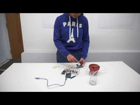
For my third milestone, I combined the water pump, the LCD, the wifi shield and the Arduino together. The Arduino would display “connecting to wifi” when it was trying to connect to the wifi. When it succeed, it would display “connected” and move on to the main menu. If the soil moisture sensor constantly measured a low value, the water pump would start working for 30 second and then stop.
At first, I followed the instructions and prepared a transistor, a resistor, and a diode to connect the water pump to the Arduino. I soldered the negative lead of the diode and a black wire to the positive pin of the water pump, so the voltage that kept the current flowing would stay at an appropriate size and it wouldn’t fry the motor or the transistor when the motor was turned off. After I finished soldering the other side, I wrap the water pump’s pin with some electric tape to prevent any possible harm. The transistor that I found was 2N3904, but the one that the instructions used was actually PN2222A. Therefore, when I connected the motor’s ground to collector, the emitter to a ground, and the base (transmitter) to a 10K resistor then to analog pin 4, the motor wouldn’t turn and the transistor was over heating. I tested the motor with my instructor and made sure that it could get worked directly with the water pump. My instructor suggested that a MOSFET would be better control the motor because it was a voltage based transistor instead of a current based transistor. If I used MOSFET, I actually didn’t need a resistor to limit the current. We then figured out that we need to connect the drain to analog pin 4, the gate to the water pump’s ground, and the source to the ground of the battery. The water pump was finally able to work with the basic code that I wrote.
I modified and added my example code to my sketch that controlled the LCD. When the soil moisture was displaying values between 0 and 200(and indicating “dry”), a counter for the water pump would increase by 1. If the counter reached 15, the water pump would start watering the plants for 30 seconds and the LCD would indicate that the motor is working. During the process, I faced the problem that the water pump won’t get completely turn off by digitalWrite(motor, LOW). I eventually solved the problem by using analogWrite instead of digitalWrite to control the motor. AnalogWrite(motor, 255) made the motor to spin and pump water to the pump, and analogWrite(motor, 0) would stop providing power to the motor and make it stop.
In the function void loop(), I added this code in…
String humidity;
if(analogRead(humPin)==0){
humidity = “ERROR”;
delay(100);
//reset the motor counter
motorStart = 2;
}
else if(analogRead(humPin) >= 0 && analogRead(humPin) <= 70){
humidity = “DRY”;
//motor counter increases by 1
motorStart += 1;
}
else if(analogRead(humPin) >=70 && analogRead(humPin) <=700){
humidity = “WET”;
//reset the motor counter
motorStart = 2;
}
else if(analogRead(humPin) > 700){
humidity = “FLOOD!”;
//reset the motor counter
motorStart = 2;
}
//control the water pump
if(motorStart >= 15){
tft.fillScreen(ILI9340_BLACK);
tft.setCursor(0, 0);
tft.setTextColor(ILI9340_BLUE);
tft.setTextSize(4);
tft.println(“Watering…”);
//make the water pump start pumping water for 30 seconds
analogWrite(motor, 255);
delay(30000);
//make the water pump stop;
analogWrite(motor, 0);
//reset the motor counter
motorStart = 0;
}
In the end, I added an brief introduction on the LCD to indicate that the wifi shield was trying to connect to the WIFI. The LCD would first print out that it is trying to connect to the wifi. If the Arduino successfully connected to wifi, it would print out “succeed!” and wait for 3 seconds before displaying the main menu. If it failed, it would print out “failed”.


![]()


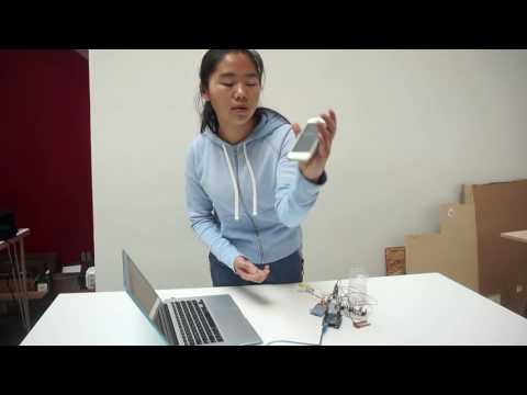
For my second milestone, I added the Wifi Shield CC3000 and a water level sensor to my Arduino. My Arduino now can send a SMS to me when the water level is low in the water container. I used TEMBOO(acting as the server between Arduino and Twilio) and TWILIO (providing phone number and services to send SMS) to work with my Arduino.
At first, I tested the water level sensor by plugging it in analog pin 2 and configuring the pin mode to output. I modified my sketch so that LCD would display the measured value on the Plant’s Status Page. When the sensor was immersed in the water to its maximum extent, the displayed value will be about 500. When the sensor was taken out from water, the value would gradually drop to 0.
After I made sure the water level sensor was working, I moved on to assemble the Adafruit wifi shield CC3000. I followed the instructions and soldered female header pins on the wifi shield. At first, I didn’t connect all the other components to the shield. I just used the example sketch from its example library to test the it.


When I connected all the components together, I faced a huge problem. The LCD and Wifi Shield were having conflicts because they both used the SPI pin and the Chip Select pin 10(Slave Select pin). With help from my instructors, I changed configuration of the LCD’s CS pin to pin 8 and its RST pin to pin 0. The wifi shield and LCD could work together now because they had their individual Slave Select pins.
Next, I signed up on TEMBOO and TWILIO, and I got a TWILIO’s phone number for my Arduino. I used TEMBOO’s Choreo (a program provided by TEMBOO) – Twilio . SMSMessages . SendSMS- to generate an example sketch based on my wifi configuration, Twilio account, and phone numbers. When I uploaded the sketch, I needed to open “TembooAccount.h” alongside the sketch in Arduino IDE. Although the shield could connect to wifi, Arduino would just display the message “http code 400 bad request” on the serial monitor. I emailed TEMBOO Support, and they suggested that my Arduino probably ran out of memory and I should use profile to store my input (Twilio account’s information, message, Arduino’s phone number and my phone number). After I used profile and deleted the unnecessary serial print statement, my Arduino could send text messages to my phone once when its measure value equals zero.


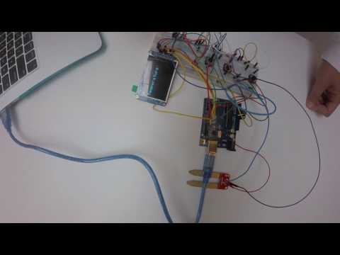
For my first milestone, I got my LCD screen, temperature sensor, humidity sensor, three buttons, and Arduino Uno to work together and display a working menu. Now, I can scroll down the three menu items and enter them by pressing the ENTER button. If I want to return back to the menu, I can press the BACK button. In the “Plant’s Status” page, the LCD screen can display values (Humidity and Temperature in both Celsius and Fahrenheit) that are collected by the two sensors.
In the beginning, I tried to just wire the LCD screen to the Arduino and make it display a testing graphic that I downloaded from the tutorial. I struggled a little bit because I wasn’t able to find the library and example code that matched the LCD. After it worked, I took some time to study the example code and learned how to display words and measured value. Then I moved on to connect the temperature sensor to Arduino’s analog pin 0. When I was writing the code, for some reason, the LCD couldn’t display the voltage nor the temperature. I eventually solved the problem by modifying the calculation of voltage and temperature in my sketch. Adding the soil humidity sensor to analog pin 1 was comparatively easier.
The next step was to use the button to exit the page (display of two values) and return to the menu (main page). This was the biggest challenge before I reached my first milestone. Almost all tutorials about buttons will make the display change and stay only when the button is pressed and held. I wanted the page to change when the button is pressed then released. Despite almost no reference from internet, I successfully achieved my goal by changing the values of different variables and using if-else statement on them. After I had ensured that the ENTER and BACK button were working properly, I started to program a menu and a scroll to select different items. This process was slightly easier because when I was trying to display humidity and temperature, I noticed that the values would overlap each other and never get erased. I modified my code so that the LCD would draw small black rectangles to “erase” the previous displayed data. I applied this experience of using small rectangles as erasers to my scroll as well.
#include “SPI.h”
#include “Adafruit_GFX.h” //the general library that enables the LCD to display text
#include “Adafruit_ILI9340.h” //the specific library for my TXT LCD ILI9340
//setup pins for sensors and buttons
int tempPin = A0;
int humPin = A1;
int waterPin = A2;
const int enterPin = 2;
const int backPin =7;
const int choosePin = 6;//configure pin for LCD(CS = 8, D/C = 9, RST = 0)
Adafruit_ILI9340 tft = Adafruit_ILI9340(8, 9, 0);
//These are global variables that determine is the button is pressed or not
int enterState; //the ENTER button that is used in most part of the menu(except the quiz)
int enterStateQ; //the ENTER button before the quiz starts
int enterStateA; //the ENTER button to confirm answer in the quiz
int chooseState; //the CURSOR button that is used in most part of the menu(except the quiz)
int chooseStateQ;
int back = 0; //the CURSOR to select answer in the quiz
//These are global variables that solve the pressed and released problem
int enter = 9; //It is set to 9 so that the LCD will display the LCD in the beginning
int choose = 0;
int quiz = 9;
//These are global variables that is used in the quiz
int quizSelect = 0;
void setup() {
Serial.begin(9600);
while (!Serial);
//make the random number generator generate differently
randomSeed(analogRead(3));
pinMode(waterPin, OUTPUT);
pinMode(humPin, OUTPUT);
//Start the LCD and make the screen display horizontally
tft.begin();
tft.setRotation(1);
//clear the screen
tft.fillScreen(ILI9340_BLACK);
}
void loop(void){
//It is configured this way so that the ENTER button can be used to perform different action in menu and in quiz
//quiz will be equal to 9 when the LCD isn’t display the quiz
//quiz will be equal to 0 when the LCD ask if a user wants to start the quiz or not
//quiz will be equal to 1 when the quiz starts
//This “if statement” controls how the ENTER and CURSOR button is used outside of the quiz
if (quiz == 9){
enterState = digitalRead(enterPin);
chooseState = digitalRead(choosePin);
}
//This controls how the CURSOR button is used to select answer in the quiz
if (quiz == 0 || quiz == 1){
chooseStateQ = digitalRead(choosePin);
}
//This controls how the ENTER button is used to start the quiz
if (quiz == 0){
enterStateQ = digitalRead(enterPin);
}
//This controls how the ENTER button is used to confirm the selected answer during the quiz
if (quiz == 1){
enterStateA = digitalRead(enterPin);
}
//when a button is pressed
if (enterState == HIGH){
//clean the screen so that new text can be printed on the LCD
tft.fillScreen(ILI9340_BLACK);
//enter is set to equal 1 to indicate that the ENTER button is pressed and released
enter = 1;
}
else if (digitalRead(backPin) == HIGH){
//I use digitalRead instead of variables for the BACK button because it only has 1 purpose(return back the main menu)
tft.fillScreen(ILI9340_BLACK);
back = 1;
}
else if (chooseState == HIGH){
//Because the LCD draw small white rectangles to select menu item, it needs to erase the previous rectangle before drawing a new one
tft.fillRect(0, 60, 30, 30, ILI9340_BLACK);
tft.fillRect(0, 90, 30, 30, ILI9340_BLACK);
tft.fillRect(0, 120, 30, 30, ILI9340_BLACK);choose += 1;delay (100);
}
if(back == 1){
//reset the variables
enter = 9;
quiz = 9;
//jump to display the menu
back = 0;
}
else if(back == 0 && enter == 9){
//displaying menu on the LCD
tft.setCursor(0, 0);
tft.setTextColor(ILI9340_MAGENTA);
tft.setTextSize(6);
tft.println(“~ MENU ~”);
tft.setCursor(30, 60);
tft.setTextColor(ILI9340_GREEN);
tft.setTextSize(3);
tft.println(“-Plant’s Status”);
tft.setCursor(30, 90);
tft.setTextColor(ILI9340_CYAN);
tft.setTextSize(3);
tft.println(“-User Page”);
tft.setCursor(30, 120);
tft.setTextColor(ILI9340_YELLOW);
tft.setTextSize(3);
tft.println(“-Quiz”);
}
//eraser for cursor
//make sure that the cursor will only display on the main menu
if(enter == 9 && back == 0){
if(choose == 0){
//select “Plant’s Status”
tft.fillRect(10, 60, 15,15, ILI9340_WHITE);
}
else if(choose == 1){
//select “User Page”
tft.fillRect(10, 90, 15,15, ILI9340_WHITE);
}
else if(choose == 2){
//select “Quiz”
tft.fillRect(10, 120, 15,15, ILI9340_WHITE);
}
}
else if(choose > 2){
//create a loop so that the cursor will return back to the top
choose = 0;
}
//calculation for temperature
float degreesC;
float degreesF;
degreesC = analogRead(tempPin) * 0.48828 – 50;
degreesF = degreesC * 1.8 + 32.0;
//text for the soil moisture
String humidity;
if(analogRead(humPin)==0){
humidity = “ERROR”;
delay(100);
}
else if(analogRead(humPin) >= 0 && analogRead(humPin) <= 70){
humidity = “DRY”;
}
else if(analogRead(humPin) >=70 && analogRead(humPin) <=700){
humidity = “WET”;
}
else if(analogRead(humPin) > 700){
humidity = “FLOOD!”;
}
//plant status
//the LCD will only display “plant’s status” when CURSOR is selecting it and ENTER is pressed
if(choose == 0 && enter == 1){
back = 3;
enter = 4;
}
if (enter == 4){
//printing on LCD
tft.setCursor(0, 0);
tft.setTextColor(ILI9340_BLUE);
tft.setTextSize(4);
tft.println(“Humidity:”);
tft.fillRect(0, 30, 320, 50, ILI9340_BLACK);
tft.setTextColor(ILI9340_WHITE);
tft.setTextSize(3);
tft.print(analogRead(humPin));
tft.print(” “);
tft.println(humidity);
tft.println();
tft.setTextColor(ILI9340_CYAN);
tft.setTextSize(4);
tft.println(“Temperature:”);
tft.fillRect(0, 110, 320, 50, ILI9340_BLACK);
tft.setTextColor(ILI9340_WHITE);
tft.setTextSize(3);
tft.print(degreesC);
tft.print(“C”);
tft.print(” “);
tft.print(degreesF);
tft.println(“F”);
tft.println();
tft.setTextColor(ILI9340_BLUE);
tft.setTextSize(4);
tft.println(“Water Level:”);
tft.fillRect(0, 190, 320, 120, ILI9340_BLACK);
tft.setTextColor(ILI9340_WHITE);
tft.setTextSize(3);
tft.print(analogRead(waterPin));
}
//user page
if(choose == 1 && enter == 1){
back = 3;
enter = 5;
}
else if(enter == 5){
tft.setCursor(0, 0);
tft.setTextColor(ILI9340_CYAN);
tft.setTextSize(4);
tft.println(“~ USER PAGE ~”);
tft.println();
tft.setTextColor(ILI9340_BLUE);
tft.setTextSize(3);
tft.print(“YOUR POINTS: “);
tft.println(userScore);
}
//quiz
//local variables used in the quiz
int quizSelectStart = 0;
int randNumberStart = 0;
int quizAnswer = 0;
int randNumber;
if(choose == 2 && enter == 1){
back = 3;
enter = 6;
}
else if (enter == 6){
tft.setCursor(0, 0);
tft.setTextColor(ILI9340_YELLOW);
tft.setTextSize(4);
tft.println(“~ QUIZ ~”);
tft.setCursor(30, 40);
tft.setTextColor(ILI9340_RED);
tft.setTextSize(3);
tft.println(“Press ENTER to Start!”);
tft.setCursor(30, 100);
tft.println(“Press BACK to Leave!”);
}
//If now the ENTER button is pressed, the quiz will start
if (enterStateQ == HIGH){
//start the quiz
quiz = 1;
//start generate a random number once (to get a random question)
randNumberStart = 1;
//make sure that this will only happen once
enterStateQ = LOW;
}
//If now the ENTER button is pressed, the selected answer will be confirmed
if (enterStateA == HIGH){
quizAnswer = 1;
}
//If now the CURSOR button is pressed, the user will be able to select the answer
if (chooseStateQ == HIGH){
quizSelectStart = 1;
}
//During the quiz(when quiz equals 1)
if (quiz == 1){
if(quizSelectStart == 1){
//select the next answer
quizSelect ++;
//make sure that it will only move to the next one
quizSelectStart = 0;
delay(100);
}
//generate the a random number once (each random number represent a question)
if (randNumberStart == 1){
randNumber = random(1,6);
//clear the screen to display question
tft.fillScreen(ILI9340_BLACK);
randNumberStart = 0;
}
//the rest are each question’s text
//the question will be displayed by using if-else statement
//if you answer the question correctly, you will get a user point(userScore += 1)
}
delay(100);
}
Here is a diagram of my menu and menu items:
 Currently, my quiz system has six question that will be randomly generated by using the random integer generator. When a question appears on my LCD, I can select my answer by pressing the cursor (it will be displayed as “Your Answer: “). Then I confirm my choice by pressing ENTER. If my answer is correct, the LCD will display that my input is the right answer and wait 5 seconds before it automatically moves on to the next question.


If my answer is wrong, the LCD will display that my input is the wrong answer and wait 5 seconds before it automatically moves on to the next question.


Every time when I answer a question correctly, I will earn one user point. I can view the total user points on “User Page”. The user points will later be used to let the water pump water the plants. Although now the points will be reset when the system restart, I believe that I will be able to let the points be stored on an online database once I connect my arduino to wifi.


My starter project is the Minty Boost Kit, which uses 2 AA batteries to provide 5V and charge devices through a USB port. This project helped me to understand and practice soldering because I needed to solder 5 resistors, 4 capacitors, an inductor, a diode, 2 AA batteries holder, an IC socket and a USB Hub on the circuit board. The resistors provide resistance to the flow of electricity and control the current flow in the circuit. The capacitors stabilize the input and output voltage by storing the energy in an electric field. The diode makes sure that the current only flows in one direction. The inductor converts low voltage to high voltage because it doesn’t like current to change. The inductor will increase the input voltage, which is 3V, to match up the output voltage, which is 5V. By increasing the voltage, it ensures that there aren’t any changes in the current. The IC chip acts as the brain for the circuit. The batteries provide power to the circuit and the USB hub charges the device that is connected through cables.

Because I didn’t have a stand to hold the circuit board, I took some time figuring out an efficient way to position the board and solder in the beginning. After I finished assembling the components, I couldn’t measure the voltage with the multimeter. I eventually found out that one of the batteries wasn’t contacting the poles on the holder. The rest of the project was comparatively easier because it just involved cutting the tin box and putting the circuit board and battering holder in it. By creating this portable battery charger, I not only learned to identify each component in the schematic, but also understood the function of each component on the circuit board.