Robot RC Tank
My main project was an RC robot tank which is controlled by a PS2 controller. I chose this project because I wanted to learn and practice electrical and mechanical engineering. I also wanted to learn about Arduino.
Engineer
Wilton Z.
Area of Interest
Electrical and Mechanical Engineering
School
Gateway High School
Grade
Incoming Junior
Final Milestone
Second Milestone
First Milestone
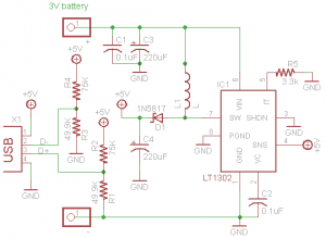
Starter Project
My Starter Project is MintyBoost Charger from Adafruit which runs on AA batteries. This includes five resisters, 2 electrolytic capacitors, 2 ceramic capacitors, one diode, an IC chip, and one inductor. The 3 volts that come from AA batteries is not enough so the device is basically a boost converter. The integrated chip takes the volts from the AA batteries and turn its switch on and off. This makes the inductor create and destroy it’s own magnetic field and reverse it polarity to maintain a constant current which leads to and increase of 5 volts. The newly increases volts are stabilized by the capacitors and the diode sends the current one way to the phone to charge.