Smart Garden
This Arduino and Raspberry-Pi based garden hardware allows for monitoring of your plants and indicates when to water it. It incorporates a soil moisture sensor, a homemade water level sensor, and a temperature and air humidity sensor.
Engineer
William K.
Area of Interest
Electrical Engineering
School
Regis Highschool
Grade
Incoming Sophomore
Final Milestone

Since my second milestone I have improved my project by integrating Raspberry Pi into my project. The Raspberry Pi is connected to the arduino through serial communications, where the arduino sends the sensor data over. The Raspberry Pi hosts a server that has a website inside, and the website shows a graph of the data from the sensors so you can monitor it as long as you are connected to the same wifi.
Second Milestone
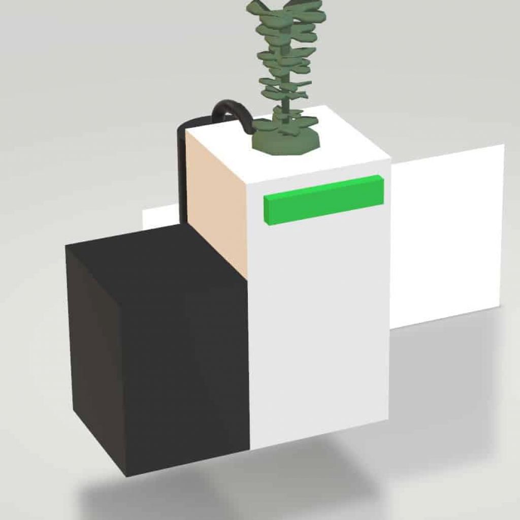
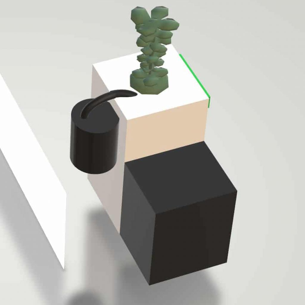

I have recently just finished my second milestone, which was to improve and build a physical body for the project. This setup has two circuits, one for the water pump, and one for the arduino and is sensors on the perfboard. The arduino circuit contains the arduino microcontroller, a homemade water level sensor, a soil moisture sensor, and a temperature + humidity combo sensor. The water level sensor consists of two galvanized nails in a wood holder (block of wood with slots in it for the nails). When the water level sensor nails are not touching a common object or liquid, the output will be 1023 because the circuit is not closed, and when they are touching a common object or liquid a legitimate output will result which can vary depending on the substance and its conductivity. The soil moisture sensor also uses the same concept as the water level sensor but is optimized for use in soil. The DHT11 humidity sensor part works using a moisture holding substance sandwiched in between two electrodes. As humidity rises the moisture holding substance absorbs water thus altering the conductivity of it which is measured and used to calculate the humidity. The temperature part of the DHT11 uses a thermistor (thermal variable resistor) that decreases resistance as temperature increases, which is then calculated for an output. The relay circuit consists of a relay, water pump and battery. The relay acts as a switch controlled by the arduino circuit. The data from the sensors is inputted into the Arduino, which runs its code. Depending on the values inputted, the arduino will decide to either run the water pump, or to leave the plant as is. As well as deciding whether the pump should be watered, it also displays the data on a front-mounted LCD.
First Milestone
Starter Project
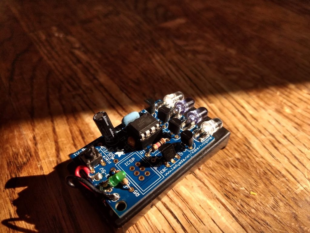
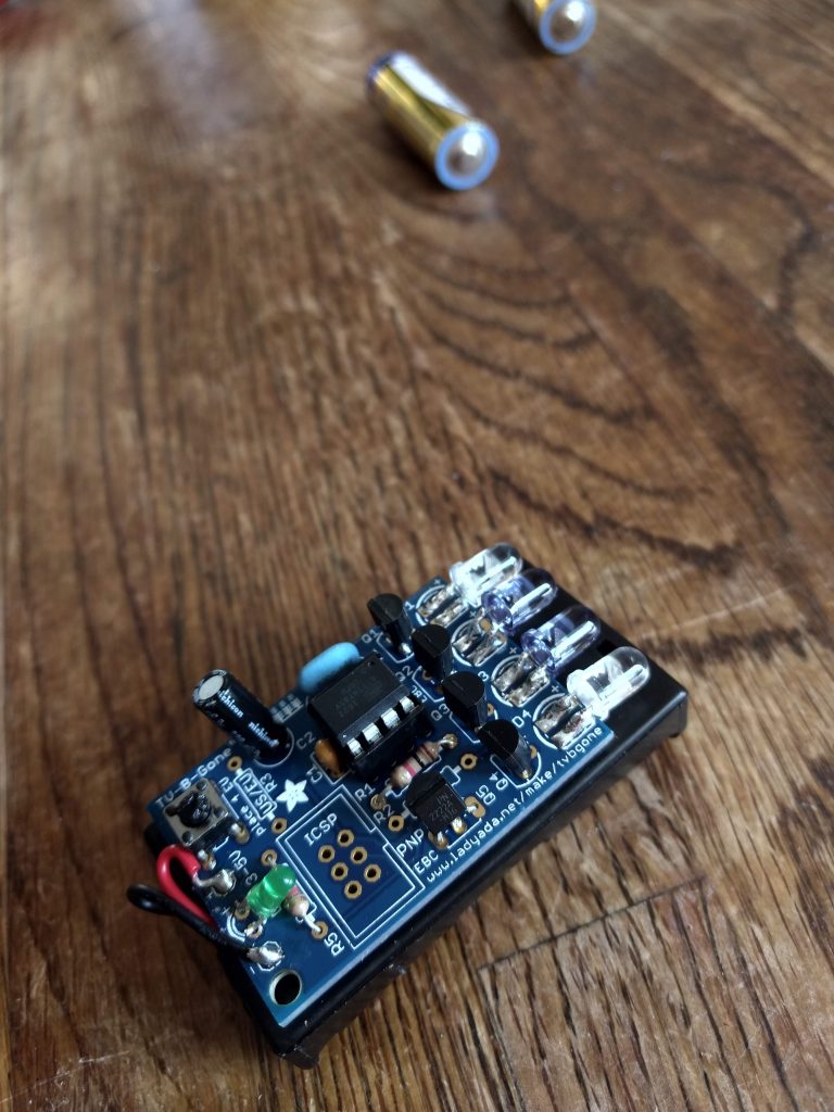
For my starter project, I made the TV-B-Gone. This module has the ability to turn off practically any TV it is pointed at. It functions through a button connected to the reset pin of a microcontroller, which when rest runs preset code (editable if an ISCP is soldered onto the board) loaded on to the microcontroller that has an 8Mhz clockspeed controlled by an external ceramic resonator. The microcontroller sends electricity to the infrared (IR) LEDs, but because the microcontroller can only send a max of 20-40 mA of electricity and the IR LEDs require 100 mA the transistors are used to amplify the electric current. The infrared LEDs emit 940 nanometer pulses of light (invisible to the human eye) that are used in TV remotes to turn off their respective TVs. The white IR LEDs emit wideband (short range but wide spread) and the blue IR LEDs emit narrowband (long range but narrow). The whole module is powered by two AA Alkaline batteries. Each TV only recognizes pulses of infrared light pulsing at their designated Kilohertz (KHz) so for the TV-B-Gone to turn off practically any TV sold in North America the microcontroller is connected to an online database for all the KHz TV frequencies.