
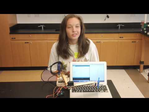
Hello! My name is Callie, and I’m a rising senior at The Dalton School. I’ve been taking computer science at school for three years and spent last summer building a bike speedometer here at Bluestamp. When choosing my project this summer, I knew that the comfortable route would be to choose another software based project. However, I wanted to branch out and challenge myself with something unfamiliar: robotics. I’m really excited about my typing robot! In the future, I hope to marry the robotics experience I’ve gained this summer with the coding skills I’m learning in school to create more challenging, smarter robots in the future.
My robot is now voice controlled! This has been a goal of mine for a long time, and I tried a lot of different ideas. I first tried to use an Easy VR Shield, which allows for voice control with pre-implemented commands, but it was a defective shield. Then, I decided that I would try to write an API (automated processing interface) to interface with Google’s voice recognition. Even though I’d never written anything as complicated as an API, I was dauntless and excited to learn! After doing research about how to write an API, I realized that there was an easier way: just use the dictation tool that comes with my Mac! I’m really excited about this voice recognition and for the opportunity it gave me to learn about APIs.
Voice Controlled Typing Robot
Final Milestone: Accuracy and Reliability!
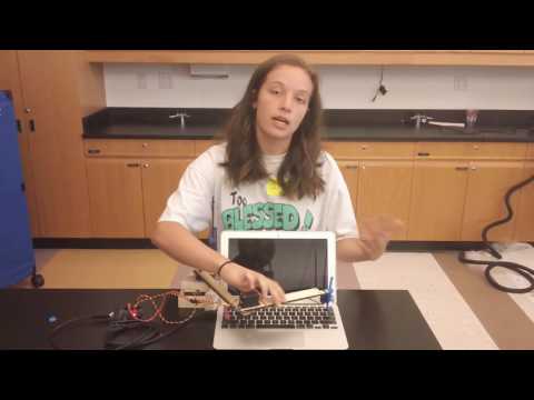
My final milestone is the increased reliability and accuracy of my robot. I ameliorated the sagging and fixed the reliability of the finger. As discussed in my second milestone, the arm sags because of weight. I put in a block of wood at the base to hold up the upper arm; this has reverberating positive effects throughout the arm. I also realized that the forearm was getting disconnected from the elbow servo’s horn because of the weight stress on the joint. Now, I make sure to constantly tighten the screws at that joint.
I increased the reliability of the finger by upgrading my rack and pinion. I replaced my old pinion that only had about 120 degrees of rotation with a new, circular pinion that can rotate the full 180 degrees as allowed by my servo. With a larger range of motion, I can ensure that the rack is always hitting the key and pushing it down with confidence.

I also found out that when I power my arduino from an outlet with 9 volts my robot is much more accurate than when I power the arduino from usb, which is only 5 volts.
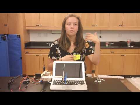
To increase the capabilities of my robot, I added in shift key capabilities so I can write capitals and special characters. I did this by placing a servo on my keyboard and moving the horn to press down on the key. I had to weigh it down with nuts to keep the pressure on the key.
Ultimately, this milestone is about tweaking the technology that I created in my first and second milestone to make it more reliable and accurate. These aspects are crucial for my project because typing inaccuracies are blatant errors and correcting them will be annoying for the user.
Third Milestone: Voice Control
My robot is now voice controlled! This has been a goal of mine for a long time, and I tried a lot of different ideas. I first tried to use an Easy VR Shield, which allows for voice control with pre-implemented commands, but it was a defective shield. Then, I decided that I would try to write an API (automated processing interface) to interface with Google’s voice recognition. Even though I’d never written anything as complicated as an API, I was dauntless and excited to learn! After doing research about how to write an API, I realized that there was an easier way: just use the dictation tool that comes with my Mac! I’m really excited about this voice recognition and for the opportunity it gave me to learn about APIs.
Second Milestone: Inverse Kinematics and Hitting the Keys
For my second milestone I mapped the keys on my keyboard and created a rack and pinion to press the keys. This means that my robot has progressed from simply an arm to a robot that knows where each and every key is, how to get there, and is able to press it.
To map the keys on my keyboard, I used a mathematical concept called inverse kinematics. Forward kinematics is a way to dictate how to get from an origin to a desired point. Inverse kinematics flips this on its head; by knowing where you want to go, inverse kinematics helps one figure out how to get there. This has applications with industrial robots and highly advanced animation softwares. If an animator want to make a character’s hand go to a certain place, how do the shoulder, elbow, and wrist joints need to move? Inverse kinematics in 3D space is incredibly interesting both because of its applications and the variety of ways the complex math behind it can be done.
Since my robot runs inverse kinematics in 2D space, I used trigonometry and coordinate geometry. If I want the robot to press a specific key, I input the cartesian coordinates of the key; I measured how many centimeters in the x- and y- directions the key is away from the base. Then, I use trigonometry to find the angles I need to set my servos to to be able to hover above the key, after which the key will be pressed by the rack and pinion. I consulted this website and then modified the algorithm to fit my frame of reference and motion needs.

This worked flawlessly for a couple days, but then the robot started to be very inaccurate; it would sometimes be two whole centimeters off. I think this is for three reasons. First, since I have the weight of my arm connected directly to the servo horns, their accuracy is compromised. Initially, the arm was smooth and accurate, but once I did a lot of testing, the weight started to take a toll on the servo. Second, these hobby servos are pretty accurate, but since a keyboard is so small and tightly packed, “pretty accurate” sometimes isn’t accurate enough; a highly accurate, more expensive servo would probably do the job better. Third, I’m doing quite a few calculations in my inverse kinematics code, which means that precision can be lost along the way. After I got over my frustration at this, I decided to rig my own code. I went key by key and adjusted the coordinates I gave the robot by a few millimeters until the math worked itself out and pointed the robot to the correct place. This was a big win.
After writing that code, I had to create my robot’s finger so I could press the keys and complete the typing task. This gave me a lot of unanticipated trouble. First I tried to press the key by attaching a branch of sorts to my micro servo, but that didn’t have enough force to press the key, especially since it wasn’t hitting the key straight on. Additionally since the arm sags, that would cause the wrong key to be pressed. Next I wanted to try a pulley, but then we realized that there would be too much inertia to have any confidence that the correct key would be pressed. I then tried to tie a string from my elbow servo to a blog of wood high above the base, but that didn’t work because since the elbow joint moves, the string would not retain tension. We then had a cool idea to use a gluestick to make a linear actuator, but then we figured that a rack and pinion would be more reliable. This series of attempts really exercised by brain and forced me to think of creative solutions and try them out.

For my next steps, I want to work on coding motion profiling, which profiles motion to make it smoother and/or more effective. I also want to make the rack and pinion more effective.
First Milestone: Physical Construction and Wiring
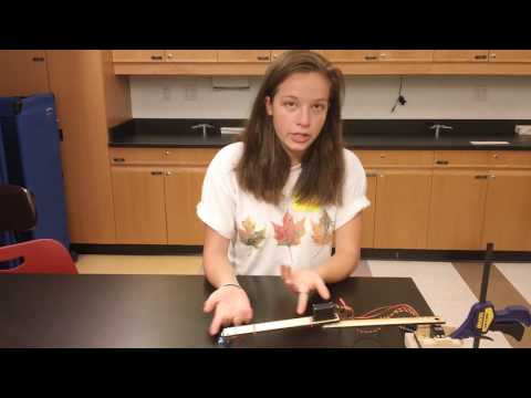
My first milestone is the finished physical construction of the main parts of my typing robotic arm. After extensive research, I chose to build a SCARA (Selectively Compliant Articulation Robotic Arm) robotic arm because this class of arms fits my needs the best. SCARA arms are best for relatively simple tasks such as tightening screws, product inspection, or moving parts a short distance. All these tasks are accomplished effectively by SCARA arms because they have incredible mobility in the x and y directions, but are more limited in the z direction (hence the name, “Selectively Compliant”). I chose a SCARA arm over a cartesian robot (an example of a cartesian robot is a 3D printer) because cartesian robots, and especially the linear motion they require, have many more variables to take into account.
I took inspiration from this Instructable when deciding how to construct my robot. To create the upper arm, forearm, parts of the base, and micro servo attachment, I used the CAD software Onshape. This was my first time using any CAD software, so I had to learn as I went. This meant that modeling took a fairly long time and was a little frustrating. However, now I feel much more confident about my 3D-modeling abilities, and I’m glad I had this introduction to CAD because laser cutting and 3D printing will be incredibly valuable to my future engineering projects.


After getting these parts laser cut, I assembled them and attached servos. With all this weight on the arm, the base was toppling over. I created supports for the servo positioned at the base and made the base heavier to balance out the weight of the arm. Clamping the base to the table does wonders for stability! I have also wired all the servos to the Arduino microcontroller and can control them with the code.
Next step: software!