Raspberry Pi Emulator
I am making an arcade machine that runs a variety of emulated retro consoles. This arcade machine runs off of the microprocessor Raspberry Pi, and I am using the Retropie operating system to do this.
Engineer
Tyler W
Area of Interest
Mechanical Engineering
School
Bellarmine College Prep
Grade
Rising Senior
Final Milestone:
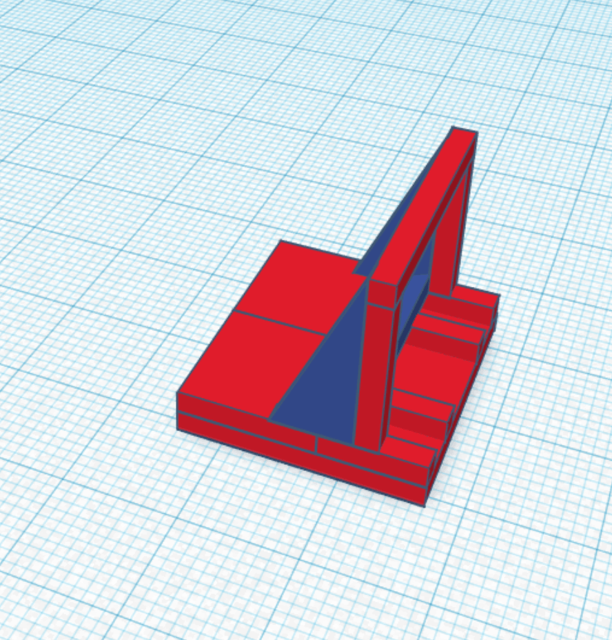
The first part of my final milestone was finishing up the side pieces of my project. This was done quickly by taking L brackets and flattening them and then attaching the triangle to the rest of the build. Each side looks like this:
I then got to making the LEDs. I started from the back and wrapped them around until I got to the platform that the joysticks were mounted on. At this point I stuck the LEDs to the top and went all the way around the perimeter until I got to the end of the other platform, where I attached them back to the side. I then went up and around the monitor, and then around the perimeter again, but this time along the bottom of it. See the final pictures for how it looks.
My last goal of this milestone was painting. I had never painted much before and I also have dysgraphia, but that did not deter me. I started by painting the red. I just used the base “Apple Red” for the color. I then went onto blue where I mixed “Admiral Blue” (dark blue) and “Caribiean” (slightly lighter than baby blue) about 1/2 and 1/2. I painted the joysticks which was a bit of a let down but that was the only thing I stuggled with there. I then had to find out how to blend the colors. I came up with the idea to create a jaged pattern for it, which worked out great!
Second Milestone
My second milestone was building the joystick for my arcade machine. The first step was to connect my xbox controller. I did this by every time I started up my pi, I ran
sudo bash -c ‘echo 1 > /sys/module/bluetooth/parameters/disable_ertm’
emulationstation #auto
which disabled something blocking the pi from connecting to the controller. Then I went and made this line of code always run at the pi boot phase so I don’t have to do it every time. It is important to note that this is only needed for the xbox controller and not for Playstation
The second step of my second milestone was to CAD the whole arcade machine so I knew where I wanted my buttons.
emulationstation #auto
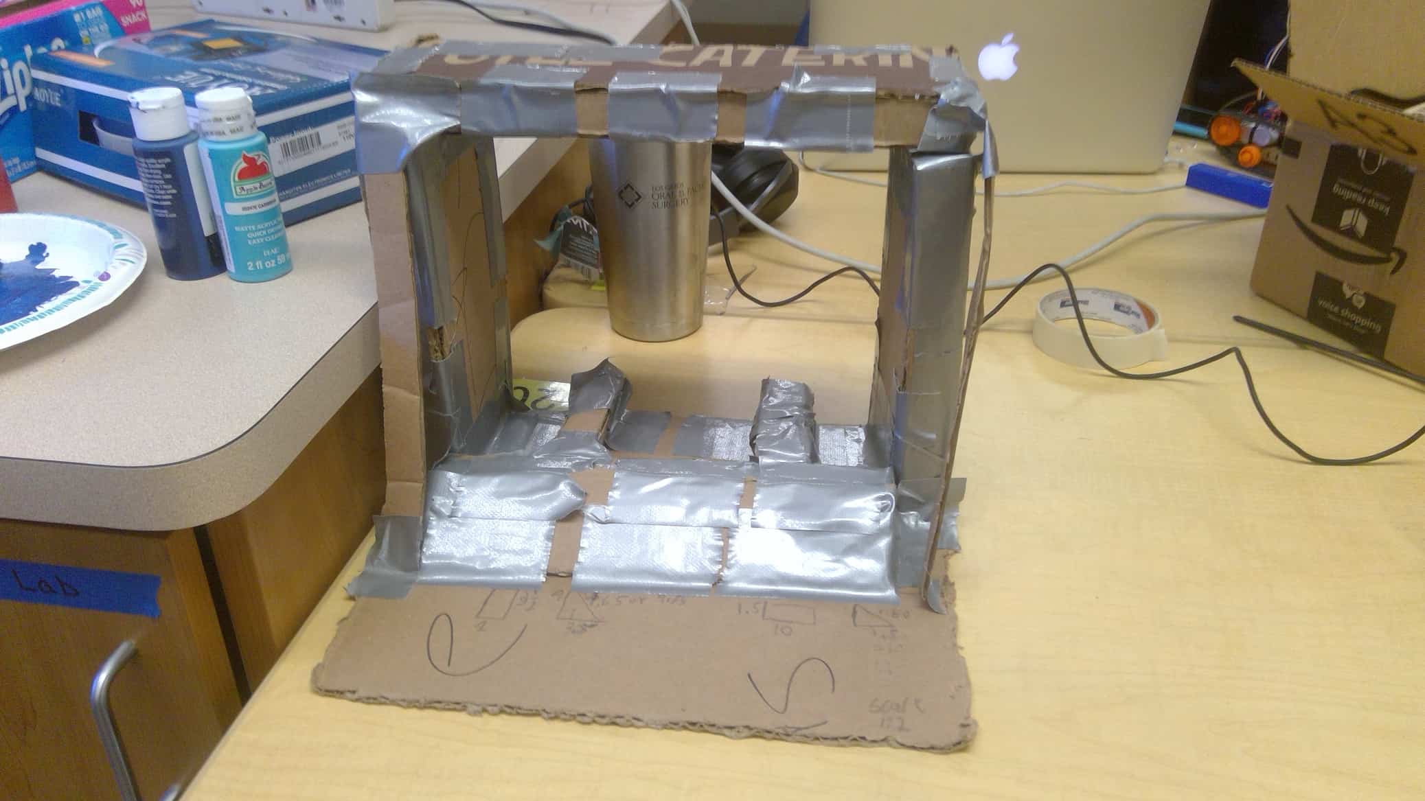
This is the first version of my machine and I made it out of cardboard

After asking a variety of people I determined the good and bad aspects of this design. The good aspects of the design included the slants all looked good, the monitor being enclosed also looked good and the monitor being raised was a good idea. The bad aspects of the design included the wood was two inches thick, which made the whole project look bulkey, the start and select buttons were both on the top with the rest of the buttons which looked off and the bottom would have been fully closed.
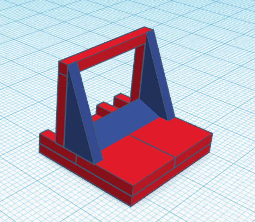
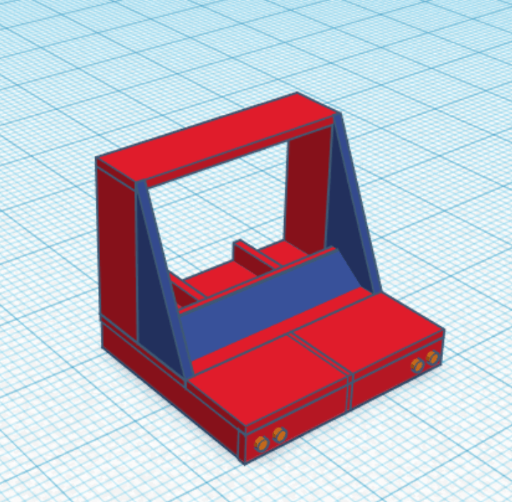
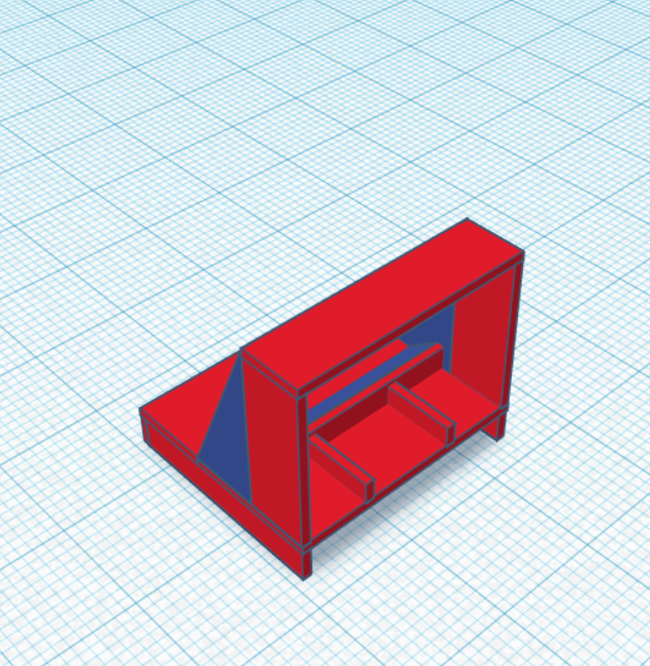
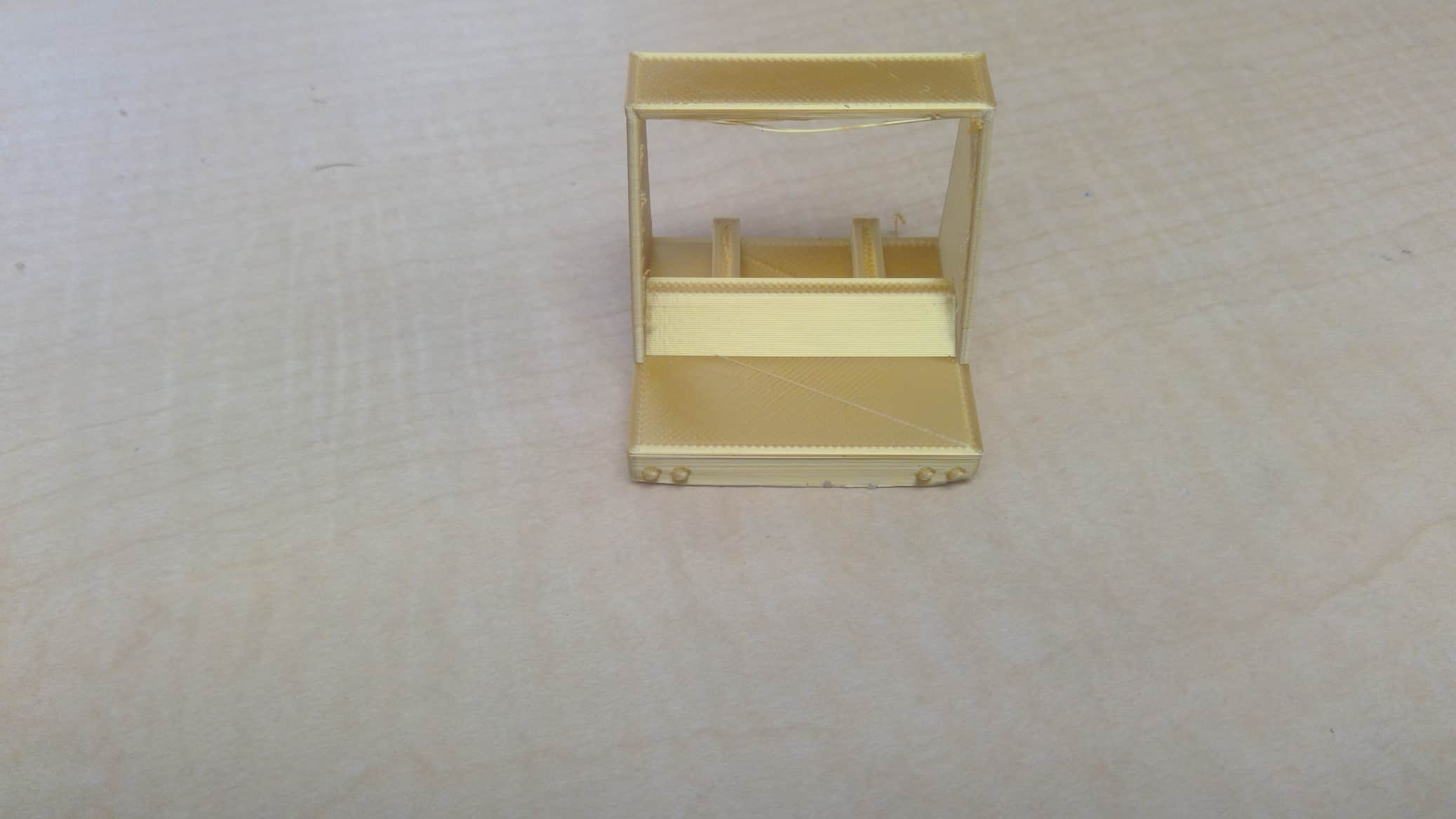
The new CAD looks like this (I also 3D printed it for no real reason besides it looks cool)
I took into concideration the criticizms of my previous model and made the wood thinner, put the start and select buttons on the front and made the bottom open. For now I did not continue to make the CAD because I had to get my main part of my milestone done, adding the buttons.
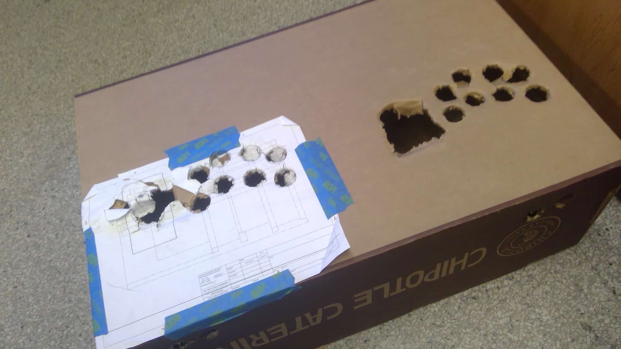
I first started my joystick by taking cardboard and making my own holes to test urgonomics, but I quickly found out that instead of guessing I could look up layouts of joysticks for actual arcade machines.
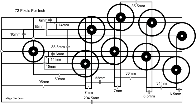
I used this webcite to find schimatics of arcade button layouts
https://www.slagcoin.com/joystick/layout.html
I ended up narrowing down the options between the standard Street Fighter layout (with two added buttons) and the “standard” Japaneese style layout first introduced by SEGA in the games Astro City and Blast City. I chose the ladder as it was more ergonomic
I ended up narrowing down the options between the standard Street Fighter layout (with two added buttons) and the “standard” Japaneese style layout first introduced by SEGA in the games Astro City and Blast City. I chose the ladder as it was more ergonomic
I then made the layout in out of cardboard
With the cardboard, I realized that the first and second buttons on the top had the posibility to overlap, but I still went on to CAD it. I used OnShape to get the exact layout of the buttons on the schematic. The person that knew how to do the CNC was only here in the mornings and 30 minutes in the afternoon, so when I sent the file it had to be perfect or we would not be able to cut it that day. I went back and forth with having the start and select buttons on the top and front, which delayed my CNC by 3 days and then when I decided on the start and select buttons on the front, I sent it over and the units were in cenemeters instead of inches meaning I had to start the schematic all over again which delayed the project another day. The CNCing of the project was delayed for a while after because of time but eventually got cut. This is a picture of the CAD file:
In the time I spent trying to CAD and CNC my buttons, I started my third milestone and final milestone, making the aracde machine. I first I made my CAD updated with the buttons on the front, after that I started with the front pannel of my arcade machine. I had the front pannels cut out on the Jigsaw, but the person that had them cut out was new to the jigsaw, so the cuts had to be sanded down in order to work. I started the buttons by measureing out the cut on the wood. After that I drilled a hole and then I expanded the hole with a dremmel. I repeated this process for the other three buttons. This was one of the first times I had dremeled so there were some lasting imperfections. I then connected the pieces of wood with a pannel of wood on the back and screwing it in, then I used wood glue to make a pannel on the front to cover the gap in between the two pieces of wood.
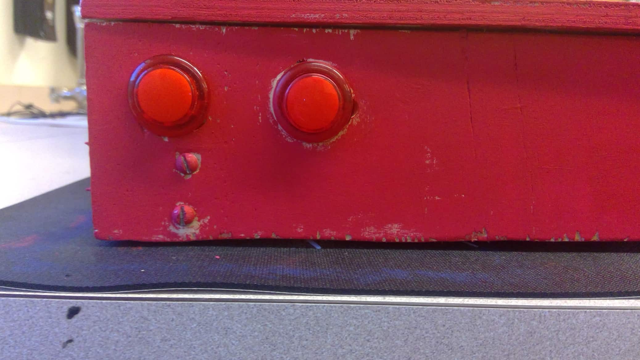
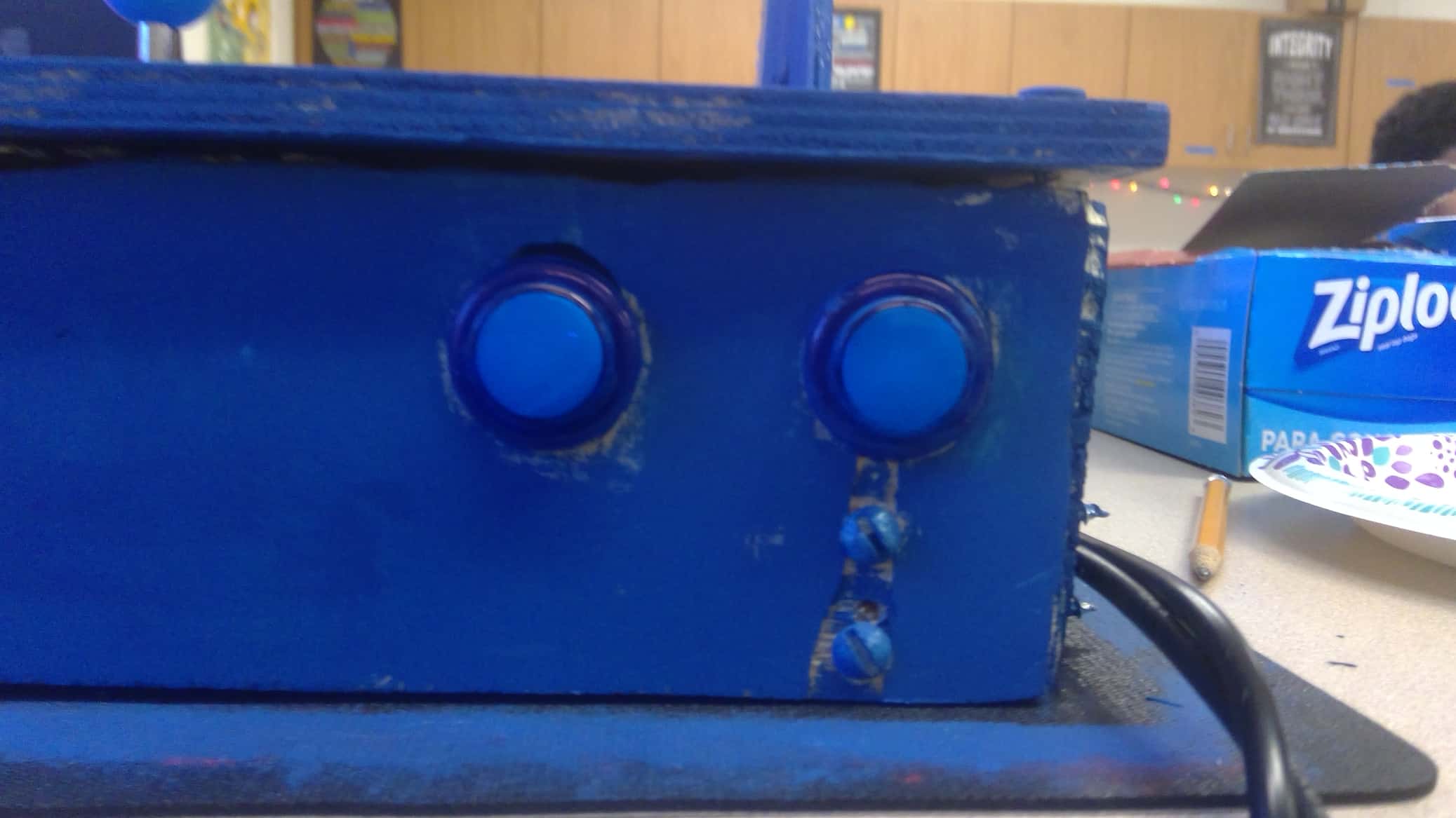
Front of project
As you can see, there are many imperfections with the buttons, specifically on the buttons closest to the center, although luckely some of the imperfections are obscured by the viewing angle. There are also imperfections with the bottom of the wood because of the poor jigsaw cut, but those are also masked by the viewing angle.
I then got a new person to jigsaw my project and they were very experienced with the jigsaw so I had no more trouble with poorly cut parts. I then attached two pieces of wood to the two sides of the front pannel. I did this by using L brackets. Unfortunately, the wood screws I used were too long and are very sharp as I am realizing now because my forearm keeps getting stabbed by them while typing. I then moved on to the upper sides of the project
Around this point I redesigned my layout of the arcade machine to drop the monitor down to the ground, as it was almost the perfect hight for the top platform.
This saved me a lot of cutting because I did not need to create the monitor holders and replaced the middle slant with a piece of wood that I can just insert into the middle and it just rests on the lip that the monitor has (see previous image for what I am talking about). I then attached the top to the sides of my project, and found out that due to the L-brackets, the wood bends past 90 degrees which makes everything look off. I cut and inserted a piece of wood for the back, that was the same length of the front pannel. It was at this point that I had my joysticks CNCed so I went back to working on that. Unfortunately, the button holes were slightly too small meaning I had to sand them and the joysticks were placed in such a way that I had to cut the one piece with two players into two separate pieces with one player each. I then dremmeled out the joystick holes to great success, and sanded the buttons to a little less success. The problem I had with my cardboard a while back came back to haunt me as the first two top buttons on player one overlap. I attached the two joysticks onto the base of my build and added the side slants.
