
My name is Tomiya, and I’m a rising senior at Lowell. My starter project is the exploding star color organ, and my main project is the voice controlled robot.
I came to Bluestamp because I wanted to know if I will pursue the right path in the near future. I want to do something I enjoy everyday, so I don’t hate my job in the future. I always wondered how certain things worked, and I wanted to know how to build these products, for example: a robot. I always liked to build and customize things. I wondered if engineering is what I want to do in the future, so I joined this program.
Reflection:
I joined this program knowing very little about engineering. Throughout the weeks in the program, I really enjoyed the hardware aspect of engineering. I learned that I can’t do one type of engineering for the rest of my life; I need to have a broad foundation in all disciplines of engineering but specialize in one type. I’m not a big fan of coding, but I would like to get better at it. I realized that some things need an all around skill set to build things. I also learned that I really want to pursue engineering in the future. I’m not quite sure about what type of engineering I want to pursue, but I’m open to anything new. Another lesson I learned from this program is that engineers learn something new everyday. I’m not sure how I feel about learning about something new everyday, but it will broaden my knowledge about engineering. I will hopefully be able to create fabulous things inside my house as a new hobby.
——————————————————————————————————————————--
Final Project

Final milestone:
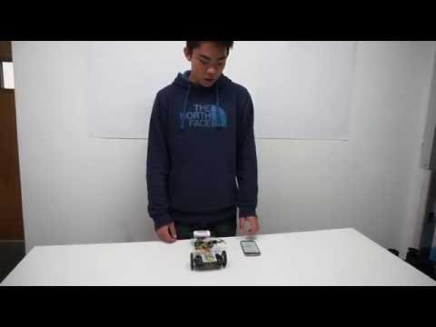
The voice controlled robot has several modifications. It has a humidity/temperature sensor (DHT11), light sensor (photocell), and a bluetooth module (HC-05). In my third milestone, I explained how I implemented the HC-05. I made an app for android devices so it can send my commands through bluetooth to the arduino. It is more effective compared to the EasyVR shield.
The humidity/temperature sensor is soldered to the proto board. Voice commands like temperature, humidity, humid, and temp will display the current temperature and humidity on the app.
How the DHT11 can display data on the app:
I programmed the arduino to print the values of my sensors in the serial monitor (a console on the computer that can’t be seen unless opened). There is something special about Serial.print (prints data values in the serial monitor) because it sends the printed messages in the serial monitor through bluetooth. My temperature and humidity sensor collects and displays data in the serial monitor. Then, the arduino sends the messages displayed in the serial monitor to the app. I made the app and the written code on the arduino to display the data values if the specified command is heard.
As an example:
If I say temperature, humidity, humid, or temp, then the app will allow the label to change into the data values displayed in the serial monitor. If i say turn right, it will not display any messages in the serial monitor, and the app will not allow any messages in the serial monitor to change the humidity/temperature label unless the command is called. Only the temperature and humidity sensor will display messages in the serial monitor. Therefore, the other commands will not display any messages on the app.
How the photocell works:
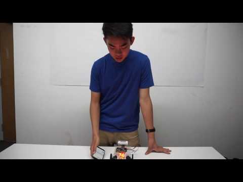
The photocell will turn on LEDs according to the values of light. I programmed my robot to turn on 4 LEDs if the robot is in a dark area, and the LEDs will not turn on if the photocell detects light. However, I can alter the code for the photocell and turn on the LEDs if the photocell detects light. Since there is no command for the photocell, I programmed the photocell to run while the robot is powered.
Code:
App:

This screenshot is a preview of the app. The file is available to download. In the zip file, I have the aia file and the apk file in the folder. The aia file is to upload the file to appinventor, and the apk file is for the android device. Drag the apk file into the android download folder and open the file with the android. The app should be ready to use after installing the app.

This screenshot is the main screen of the app. The pick a device button is used to connect to the bluetooth module. The voice command button allows the user to say a command, and the app will print the text of the command in the textbox. The app will automatically send the command through bluetooth. The restart button switches to screen one which is similar to a title screen.

Arduino:
#include “dht.h”
//DHT11 (temperature/humidity sensor)
dht DHT;
#define DHT11_PIN 8//servo
//PWM: 3, 5, 6, 9, 10, and 11.
Servo servoR;
Servo servoL;
int sR = 5;
int sL = 6;
int midR = 95;
int midL = 92;
//photocell (light sensor)
int pC = 0; // will be used for analog 0. (photocell)
int pCValue = 0; // value of output
int pC_Input = 200; // value of when light is on//leds
int green = 2;
int orangeR = 4;
int orangeL = 9;
int white = 3;
int red = 7;//commands
//1 = forward
//2 = right
//3 = left
//4 = backward
//5 = leds on
//6 = leds off
//7 = stop
//8 = counterClockwise
//9 = clockwise
//10 = humidity and temperature//Celsius to Fahrenheit conversion
double Fahrenheit(double celsius)
{
return 1.8 * celsius + 32;
}
void setup()
{
Serial.begin(9600); //opens serial port, sets data rate to 9600 bps
Serial.println(“DHT11 Detected”);pinMode(pC,INPUT);
//Serial.println(pC);
//leds
pinMode(green,OUTPUT);
pinMode(orangeR,OUTPUT);
pinMode(orangeL,OUTPUT);
pinMode(white,OUTPUT);
pinMode(red,OUTPUT);
//servos
pinMode(sR,OUTPUT);
pinMode(sL,OUTPUT);
servoR.attach(sR);
servoL.attach(sL);
servoR.write(midR); //set servoR to mid point
servoL.write(midL); //set servoL to mid point
/*
For example, the Servo1.write(0) function will make the servomotor spin counter-clockwise at full speed.
The Servo1.write(90) function will stop the motor and Servo1.write(180) will turn the motor clockwise at full speed.
On standard servos a parameter value of 1000 is fully counter-clockwise, 2000 is fully clockwise, and 1500 is in the middle.
*/
//setup sequence
digitalWrite(green,HIGH); //green
delay(500);
digitalWrite(orangeR,HIGH); //right
digitalWrite(orangeL,HIGH); //left
delay(500);
digitalWrite(white,HIGH); //white
delay(500);
digitalWrite(red,HIGH); //red
delay(1500);
digitalWrite(white,LOW);
digitalWrite(orangeR,LOW);
digitalWrite(orangeL,LOW);
digitalWrite(red,LOW);
delay(500);
}
void loop()
{
int chk = DHT.read11(DHT11_PIN);
//photocell
pCValue = analogRead(pC);
//Serial.println(pCValue); //prints photoresistor value
delay(500); // value updated every 0.1 second.
if (pCValue < pC_Input) // if sensor value is less than 100, light will turn on.
{
digitalWrite(orangeR,HIGH);//LED on
digitalWrite(orangeL,HIGH);
//digitalWrite(orangeR,LOW);// LED off
//digitalWrite(orangeL,LOW);
}
else
{
digitalWrite(orangeR,LOW);// LED off
digitalWrite(orangeL,LOW);
//digitalWrite(orangeR,HIGH);//LED on
//digitalWrite(orangeL,HIGH);
}
if(Serial.available())
{
int serialA = Serial.read();
switch(serialA)
{
case 1: //forward
digitalWrite(green,LOW);
digitalWrite(green,HIGH);
servoR.write(180);
servoL.write(0);
delay(2000);
servoR.write(midR);
servoL.write(midL);
delay(1000);
digitalWrite(green,LOW);
digitalWrite(green,HIGH);
break;
case 2: //right
digitalWrite(green,LOW);
digitalWrite(orangeR,HIGH);
servoR.write(0);
servoL.write(0);
delay(800);
servoR.write(midR);
servoL.write(midL);
delay(1000);
digitalWrite(orangeR,LOW);
digitalWrite(green,HIGH);
break;
case 3: //left
digitalWrite(green,LOW);
digitalWrite(orangeL,HIGH);
servoR.write(180);
servoL.write(180);
delay(800);
servoR.write(midR);
servoL.write(midL);
delay(1000);
digitalWrite(orangeL,LOW);
digitalWrite(green,HIGH);
break;
case 4: //backward
digitalWrite(green,LOW);
digitalWrite(red,HIGH);
servoR.write(0);
servoL.write(180);
delay(2000);
servoR.write(midR);
servoL.write(midL);
delay(1000);
digitalWrite(red,LOW);
digitalWrite(green,HIGH);
break;
case 5: //leds on
digitalWrite(green,LOW);
delay(1000);
digitalWrite(green,HIGH);
digitalWrite(orangeR,HIGH);
digitalWrite(orangeL,HIGH);
digitalWrite(white,HIGH);
digitalWrite(red,HIGH);
delay(2000);
case 6: //leds off
digitalWrite(green,LOW);
delay(500);
digitalWrite(white,LOW);
digitalWrite(orangeR,LOW);
digitalWrite(orangeL,LOW);
digitalWrite(red,LOW);
delay(1000);
digitalWrite(green,HIGH);
break;
case 7: //stop
digitalWrite(green,LOW);
digitalWrite(red,HIGH);
delay(1000);
servoR.write(midR);
servoL.write(midL);
digitalWrite(red,LOW);
delay(1000);
digitalWrite(green,HIGH);
break;
case 8: //counterclockwise
digitalWrite(green,LOW);
digitalWrite(orangeL,HIGH);
servoR.write(180);
servoL.write(180);
delay(2900);
servoR.write(midR);
servoL.write(midL);
delay(1000);
digitalWrite(orangeL,LOW);
digitalWrite(green,HIGH);
break;
case 9: //clockwise
digitalWrite(green,LOW);
digitalWrite(orangeR,HIGH);
servoR.write(0);
servoL.write(0);
delay(3000);
servoR.write(midR);
servoL.write(midL);
delay(1000);
digitalWrite(orangeR,LOW);
digitalWrite(green,HIGH);
break;
case 10: //humidity and temperature
digitalWrite(green,LOW);
digitalWrite(red,HIGH);
digitalWrite(green,HIGH);
delay(1000);
Serial.print(“Humidity ” );
Serial.print(DHT.humidity, 1);
Serial.println(“%”);
Serial.print(“Temparature “);
Serial.print(Fahrenheit(DHT.temperature), 1);
Serial.println(” F”);
delay(1000);
digitalWrite(red,LOW);
digitalWrite(green,LOW);
delay(1000);
digitalWrite(green,HIGH);
break;
}
}
}
This file should be opened with arduino ide.
What the robot can do:
- move forward, right, left, backwards
- spin counterclockwise and clockwise
- turn on LEDs and turn off LEDs
- display temperature and humidity readings on the app
Bill of Materials:
tomiya muraki bluestamp bill of materials
Electrical Schematic:

——————————————————————————————————————————--
Third milestone:
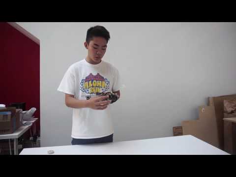
I finally completed my voice controlled robot. The EasyVR shield is very inefficient because it is very particular about the tone of the command, and if there is some background noise, the EasyVR will not recognize the command. Additionally, the servos twitched while the robot was waiting for a command. It didn’t twitch randomly, but periodically. I believe the code generated from the EasyVR commander is the source of the problem. Instead of using the EasyVR shield, I made an app that sends my command over bluetooth to the robot. This app is only available for android devices.
How the app works:
The app checks if the android’s bluetooth is on. If bluetooth is enabled, then there is a list picker (looks like a button) that can choose a device to connect to. However, the user needs to pair with the HC-05 (bluetooth module) before entering the app. After a successful connection with the HC-05, the user can send a command by clicking on the voice command button. This button allows the user to speak and converts the voice command to text and displays it in the text box. The voice command button also checks for keywords when the user gives a command. If the keyword matches any of the keywords in the app, the app sends a data character instead of the string (a list of words or word) through bluetooth to the arduino.
After the arduino receives a data character from the app, it matches the data character to one of the functions. Then the arduino performs the specified function and the robot responds accordingly.
As an example:
If the data character 1 is sent, then case 1 will be performed. Case 1 is a function for a certain command. for my code, case 1 refers to forward, which moves the robot forward.
After using the app, the servos don’t twitch while waiting for a command. The app fixed the mic issue and the twitching issue.
Electrical Schematic:

My continuous servos broke because I powered it with 8v when it should’ve been 4v-6v. I realized this mistake after my servos broke.
I decided to make an app for non continuous servos and continuous servos. I also have separate code for the non continuous servos as well. For the non continuous servos, the movement is really restricted because it can only turn 180 degrees. I made 3 patterns for the non continuous servos.
——————————————————————————————————————————--
Second milestone:
My voice controlled robot is almost complete. I have the servos, LEDs, and my arduino mounted to the acrylic baseplate. I made many mistakes during this process. First, I had to fix the circuitry for the LEDs and servos because I didn’t wire them correctly. Second, I had to re-drill all the holes on the acrylic because I cracked my original piece. Third, I had to order a new pair of servos because the original servos were 90 degree servos. This means that it only rotates 180 degrees. I finally completed my chassis using continuous servos.
I have 5 pairs of LEDs wired in series. Each pair of LEDs responds to a specific command, excluding for the backward and stop commands. The EasyVR shield is mounted directly to the arduino uno. The proto board has 10 LEDs and is connected to the servos and the arduino. The caster is attached to the end of the robot while the servos are mounted to the front of the robot. The battery will be mounted to the acrylic using doubled sided tape.
Electrical Schematic:

In this schematic, I didn’t show the EasyVR shield. I didn’t show the EasyVR shield because it has the same exact pins as the arduino uno. The EasyVR is mounted directly to the arduino. There is a picture of the EasyVR and the arduino in the first milestone.
——————————————————————————————————————————--
First milestone for voice controlled robot:

After overcoming many problems, my voice recognition software recognizes and responds to my commands. The EasyVR commander could not connect to the arduino and EasyVR shield. If you don’t know what the EasyVR commander is, it is a program affiliated with the EasyVR shield. It records commands and compares it to the user’s voice. I fixed the problem by following these steps:
1. Made sure the EasyVR shield was properly connected to the arduino uno
2. Set the mode jumper to sw
3. Connected the arduino to a computer and opened the arduino ide
4. Uploaded a sketch from easyVR bridge
5. Changed the mode jumper to pc
6. Opened EasyVR commander
7. Made sure the port com __ was the same as the arduino
8. Pressed connect and recorded my trigger
9. Went to a separate group and recorded other commands
10. Generated the code from easyVR commander
11. Opened it with arduino
12. Tweaked the code a little so the command does what I want it to do
Example code:
Group = GROUP_0;
digitalWrite(11,HIGH);
I ran into another problem because I forgot to declare the LED as an output pin.
Example code:
pinMode(11,OUTPUT); //in the setup function
“Hello” triggers the robot to listen to my following command, and turns the LED on. “Light on” turns off the LED because the LED is already on, but turns on the LED right after a second delay. “Turn off” turns off the LED.
How it works:
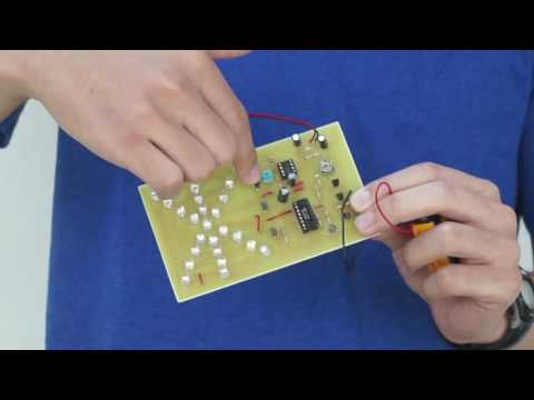
The arduino uno is a microcontroller and is connected to the EasyVR shield. The LED is connected to ground and a digital pin. A program called EasyVR commander records my voice and generates code for the functions in the voice recognition software. I had to edit the code inside the command functions so the robot would respond to a command. I edited the “light on” and “turn off” functions. These two functions control the LED.

In this picture, I had the LED in pin 11 and in ground. This is not the correct way to power an LED. The LED should have a resistor.
——————————————————————————————————————————--
Exploding Star Color Organ Kit
The light organ is powered by a 9v battery. The mic picks up sound and sends the signals to the three transistors which amplify the signal strength to the IC1. The IC1 is activated and sends a series of clock pulses to IC2. The IC2 sends the clock pulses to the four output transistors that control a group of 6 LEDs. The last LED is controlled by the IC2, which has an output pin tied directly to the led in the center of the led display. The potentiometers can be adjusted to change the resistance within the circuit. The resistors and capacitors regulate the circuit to prevent any short circuits.