FPV Car
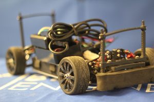
My project is to computerize the control of a remote controlled car, and then be able to view a video feed from the car over the internet.
Engineer
Thomas N.
Area of Interest
Computer Science
School
Regis High School
Grade
Incoming Sophomore
Reflection
Before this summer, I have always enjoyed working with computers and electronics, and I learned a lot by reading articles online. However, I had little hands-on experience, and I never really had the electronics skills to complete a major project. Over the past 5 weeks, I quickly learned that engineering requires a lot of perseverance, but is incredibly rewarding when you finally see your project work. I also learned a lot about practical engineering, such as how to solder properly, how to use various components like resistors and capacitors to manipulate a flow of electricity in a circuit, and how much you can accomplish with a few electronic parts, a microcontroller, and the internet. I am now also a lot more excited about engineering, and I would like to spend more of my free time working on engineering projects, like a quadcopter I am building right now. I would also like to study computer science in college and later on.
Final Milestone
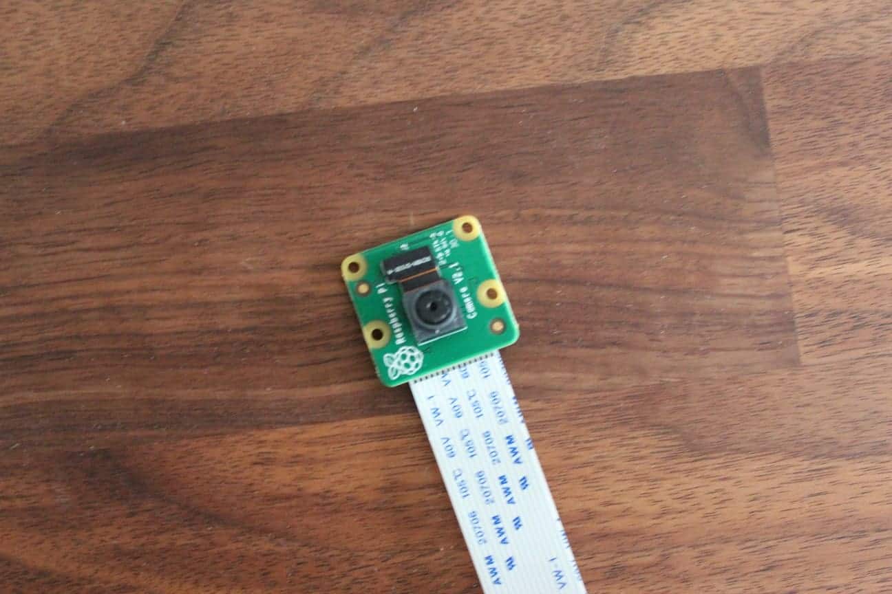
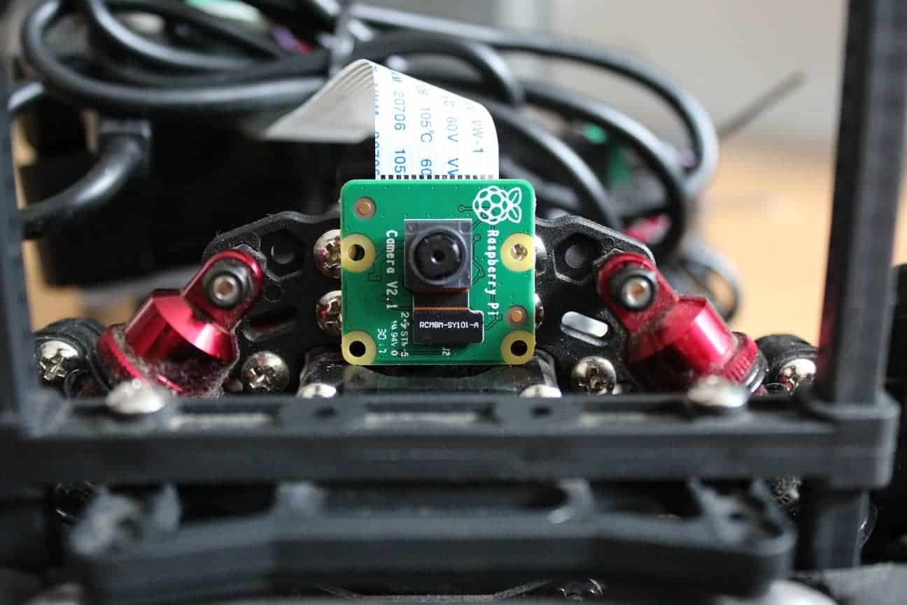
For my final milestone, I added a Raspberry Pi camera to the front of the car. By adding a camera, the car can be controlled in first person view, even in another room. I used a Raspberry Pi plugin, the RPi-Cam-Web-Interface (https://elinux.org/RPi-Cam-Web-Interface) to send the video signal from the Raspberry Pi, which can be accessed by entering the Pi’s IP address on a computer on the same network.
Second Milestone
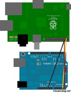
For my second milestone, I established communication between the Raspberry Pi and the Arduino. Since the Arduino is only there to give the servo and motor speed commands and is only capable of simpler tasks, I am using the Raspberry Pi to run the camera and internet parts of the project. Essentially, the Raspberry Pi can send a value between 1 and 100 for the steering and for the throttle. The Arduino then maps these values to the actual scale of the servo and the motor. Unfortunately, getting the devices to communicate was quite difficult and took me two weeks, as I was constantly running into problems. My first attempt was to use serial communication, which is a communication interface over USB. While theoretically the simplest, serial communication would never work properly or consistently, printing out the wrong values or not transmitting at all. I then tried I2C, which uses three wires between the Raspberry Pi and the Arduino to communicate. I2C, or inter-integrated circuit communication, is usually a protocol for components on the same circuit board, or, in this case, for two separate computers, to communicate.
import smbus, time, keyboard
bus = smbus.SMBus(1)
address = 0x05
i = 1
x = 50
y = 1

def i2c():
    a = keyboard.is_pressed('a')
    d = keyboard.is_pressed('d')
    w = keyboard.is_pressed('w')
    if (a == True):
        x = 1
    elif (d == True):
        x = 100
    else:
        x = 50
    if (w == True):
        y = 40
    else:
        y = 1
    try:
       bus.write_word_data(0x05, 0x98, x)
       time.sleep(0.02)
    except IOError:
       i2c()
    try:
       bus.write_word_data(0x05, 0x99, y)
       time.sleep(0.02)
    except IOError:
       i2c()
    a = False
    d = False
    w = False

while i == 1:
    try:
        i2c()
    except IOError:
        i2c()
#include <Servo.h>
#include <Wire.h>
#define SLAVE_ADDRESS 0x05
Servo motor;
Servo servo;
int Speed = 0;
int Angle = 93;
int steering = 0;
int throttle = 0;
char char1;
char char2;
char char3;
char char4;
int receive;
int x;
int y;
void setup() {
motor.attach(10); //Setup motors, insert the digital pin that each is connected to
servo.attach(11);
motor.writeMicroseconds(1500); //Arming pulse for my ESC, varies for each
delay(5000);
Serial.begin(9600); //Only needed for printing to serial monitor
servo.write(93);
delay(2000);
Wire.begin(5); //Start i2c
Wire.onReceive(Receive);
}
void loop() {
delay(5);
control();
}
void Receive(int howMany) {
while(Wire.available()){
int receive = Wire.read();
if (receive < 101 && receive != 0){ //Looks for command values
x = receive;
}
else if (receive == 152){ //152 = hexadecimal of 98
throttle = x;
}
else if (receive == 153){ //153 = hexadecimal of 99
steering = x;
}
Angle = map(steering, 1, 100, 58, 127); //Map 0-100 steering values to angles
Speed = map(throttle, 1, 100, 1565 ,1700); //Map 0-100 to PWM range for the motor
Serial.println(steering);
}
}
void control() {
servo.write(Angle);
motor.write(Speed);
}
I then used the SMBus library in Python to send the values from the Pi to the Arduino. Specifically, using the bus.write_word_data() function. With this function, I can send another value along with the actual value I want to send, 99 for steering, and 98 for throttle. For instance, if I sent bus.write_word_data(0x5, 99, 50) from the Pi, the arduino would decode that the steering should be 50, in the middle. This way, in the Arduino code, I can distinguish whether the value is for steering or for throttle.
Unfortunately, I2C would disconnect and fail after anywhere from a few seconds to a few minutes, causing Python to crash. I tried a few different things, like increasing delays and checking for electrical noise, but I eventually figured out that I can use the Try and Except functions in Python to detect when the error occurs, and restart the function.
try:
i2c()
except IOError:
i2c()
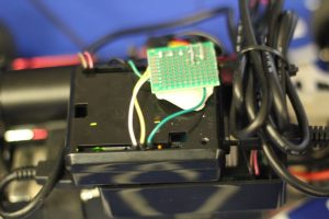
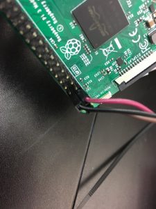
Finally, I organized the wiring and attached the computers to the car inside of their respective cases, and soldered all of the connections to make a compact and clean build.
i2c()
except IOError:
i2c()