
Introduction
Hi, I’m Kathleen and I am a rising senior at Castilleja School. For my project I decided to build the tiny wanderer (a table top robot) based on this instructable. I chose this project because I wanted to do a bit of everything, mechanical engineering, electronics, and programming, and because robots are always super cool.
I had some experience with engineering before Bluestamp through FIRST Robotics, but I wanted to do Bluestamp to see if engineering was something I was really passionate about. During the first few days of Bluestamp I had no idea how I was going to build my project and it felt very overwhelming. However, through a lot of research, trial and error, and some helpful tips from the instructors I ended up with a working robot. Throughout the program I gained so much confidence in my ability to problem solve and figure out the answers to my questions myself. I had so much fun with all parts of my project, and I am excited to do more engineering in the future.
Code, Schematics, BOM, etc.
Code – this is a link to my Github repository with the final code for both my robot and controller.
Laser cutter files – click here to go to a google drive folder which contains dxf and pdf versions of the laser cutter files. These files are from this instructable, which was the basis for my project.
BOM – this is the link to the bill of materials for my robot.
Schematic – This is a link to the schematic for my project. The left side is the schematic for the circuit on my robot. The right side is the schematic for my controller circuit.

Overview:
My robot has 4 sensor pairs composed of an infrared emitter and an infrared detector. There is an emitter and detector pair at each corner of my robot; they work together to sense if the table is below the robot. If one of the sensor pairs does not sense the table it will tell the robot to move in a certain direction to stay on the table. Both my robot and my remote use an Arduino Leonardo as the micro controller. Both have shields on top of the Arduino which host an XBee. The two XBees are what allow the remote and robot to communicate wirelessly. The XBee on the remote sends signals to the XBee on the robot, telling the robot what to do. For more information on how my robot works and the process I went through to build it, continuing reading.
Final Milestone:
For my final milestone I added modifications to my robot. The first modification I decided to add was remote control. To this this I had to use XBees so the remote could communicate wirelessly with my robot. Other Bluestamp students who have Macs could not configure the XBees on their computers. So I used another student’s PC to configure my XBees. I realized now I might have been able to configure them on CoolTerm, so if I have to configure XBees on my Mac I will try that. After configuring my XBees I struggled to get them working because I am using an Arduino Leonardo not UNO. There is a switch on the XBee shield I was using had a DLINE option and a UART option. The UNO needs the switch on the DLINE option, but the Leonardo needs the switch on the UART option. The other difference was UNO’s use the software serial Arduino library for the XBees to communicate whereas the Leonardo uses Serial1. Most of the instructional guides I was reading were for the UNO so it took me some time to figure out these issues and get the XBees working.
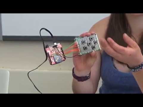
Once the XBees were working I kept the coordinator on a dongle plugged into my computer and used my computer keys to control my robot. Once I was confident that was working I set up a circuit with pushbuttons to make an actual controller. Each pushbutton has for legs, and I connected 3 to the Arduino. One to power, one to ground through a resistor, and the third to a digital I/O pin. When the button is pressed current can flow from power to ground, and the button gives a reading of high. If a button reads high, the XBee on the controller sends a direction to the XBee on the remote depending on which button is pushed.
Once the remote control was implemented I decided to also add voice control. Originally I wanted to use a Sparkfun easy voice control shield, but that would only work with a PC, not a Mac. I found a way to use software on the Mac to add voice control. I created some applications using automator on my computer. When one of the applications is run it sends a command to the remote Arduino through the serial port on my laptop. Then, just like a button was pushed, the XBee on the remote sends a command to the robot. To make these applications voice activated, I used the dictation function on accessibility in system preferences. This allowed me to tell my computer to run an application when a certain word is said. So when I say backward, run the application that sends the backward command to the remote.
I originally wanted to connect my remote to my computer through bluetooth so the remote would not need to be connected to the computer with a cord. Unfortunately I did not have time to implement the bluetooth, so my remote needs to remain connected to my computer for voice control to work. However, if I just want to control my computer with the remote only a power supply is needed.
Milestone #2:
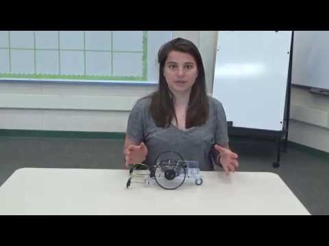
My second milestone was assembling the robot and mounting the circuit I already built to get a working robot. As you can see in the video, it can now drive around the table without falling off. The robot is mostly made of acrylic and getting the acrylic here was a challenge in and of itself. The files from the instructable I was using were in a .svg format when I downloaded them, and that format did not provide dimensions. I did some research to find a program that I could import the files to in order to get dimensions. I found inkscape, downloaded it and was able to export them as .dxf’s to send to the laser cutter. Unfortunately, the dimensions did not show up correctly when the person who was laser cutting my parts opened them on his computer (they were scaled super large and he didn’t have enough acrylic). I got on the phone with him and sorted out the measurements, after that I just had to wait for the pieces to arrive.
Once they arrived assembling the chassis involved putting a lot of nuts and bolts together. Attaching the servo horn to the wheels actually presented some difficulty because the horns had no way to connect to the wheels, so I had to drill holes in them and bolt them to the wheels.
After assembling my chassis it was time to figure out how to mount my electronics which was hard because there is not much space on my robot. I noticed that the shield for my Arduino that I got to implement my XBees has prototyping space so I was able to solder my circuit on there instead of mounting a separate PCB. I had to disassemble my chassis and drill holes to mount my Arduino, and I glued my IR sensors to the front of the robot. I used a rubber band to mount my lithium ion battery and electrical tape to make my wires so they would not be all over the place.
Here is a schematic for the circuit on my robot:

Milestone #1:
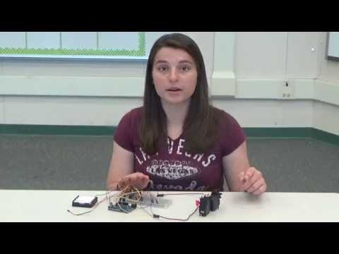
My first milestone was completing the circuit that will be on my robot. This involved learning how to connect servos and infrared emitters and detectors to an Arduino, which is the microcontroller I am using, and programming them. For the servos, it was fairly simple there are three wires a power, ground, and signal wire that can be connected to the Arduino. Code for the servos was next. There is a servo library which contains the write() function. You can pass in numbers from 0- 180. 0 being full speed one way, 90 being stop, and 180 being full speed the other way.
Next was the infrared emitter and detector. This initially presented some challenges because it was hard to determine exactly how to set them up. Eventually I was able to read the schematic on a instructable I found. I connected the anode (positive) pin of the detector to power (through a resistor) and an analog input signal pin. I connected the cathode (negative) pin to ground. For the emitter the anode is connected to a digital signal output pin, which is just one of the digital input/output pins on the Arduino that is configured to be output in the code. The cathode is connected to ground. The way distance is measured is the detector measures infrared light when the emitter is off, and a again when the emitter is on and takes the difference.
Everything is powered by the battery back. Currently I have some simple code on the Arduino. When the sensors sense something close (the table) they will drive forward, when they don’t sense anything they will back up, and then drive forward again.
My next milestone is actually assembling the robot.