Third Eye For The Blind
The Third Eye for the Blind is meant to help blind individuals to navigate their environment without any harm. It senses how far away an object is. If it is less than 50 cm away the Piezo buzzer or the vibrating motor(chosen by a flip switch) will activate. The 3D mapping comes from the frequency of the buzzing; as it gets closer to an object, the buzzing gets faster.
Engineer
Sunskar Dhanker
Area of Interest
Computer Science/Hardware Engineering
School
Monte Vista High School
Grade
Incoming Senior
Final Milestone
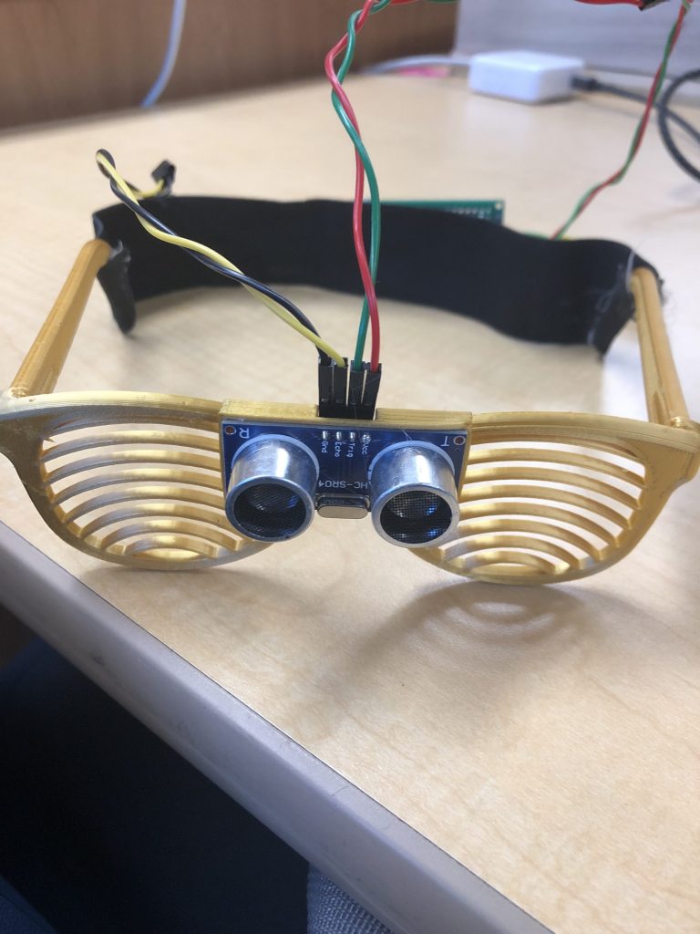
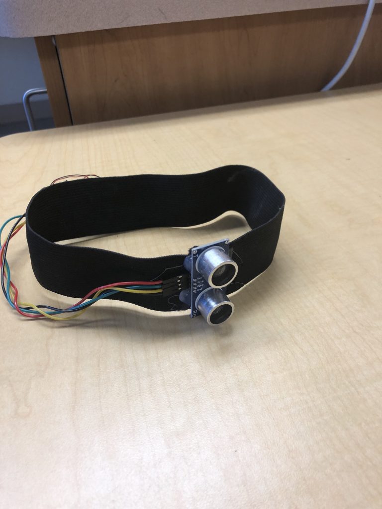
In my modificaiton milestone I faced many challenges. I had to design a sunglass 3D model. I found a basic frame online and created a small bracket to fit the ultra sonic sensor on to the glasses. I also had to find a way to make the knee band. The two quick and feasible options were to but a knee brace and fit it on there or to create a knee band with the elastic band. I chose the elastic band because the band was cheaper and was easier to put on. The circuit is very similar to the glove so there was no problem there.
Next I will be adding a bone inductor. The bone inductor will shake your skull so you will hear sound but no one else can. I will also connect all the different modules with nRFs. By connecting them I will send a notification to the bone inductor on the glasses and then the piezo buzzer or the vibrating motor will only notify which body part is close to the object. This creates another safety feature.
Third Milestone
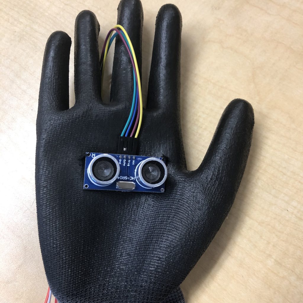
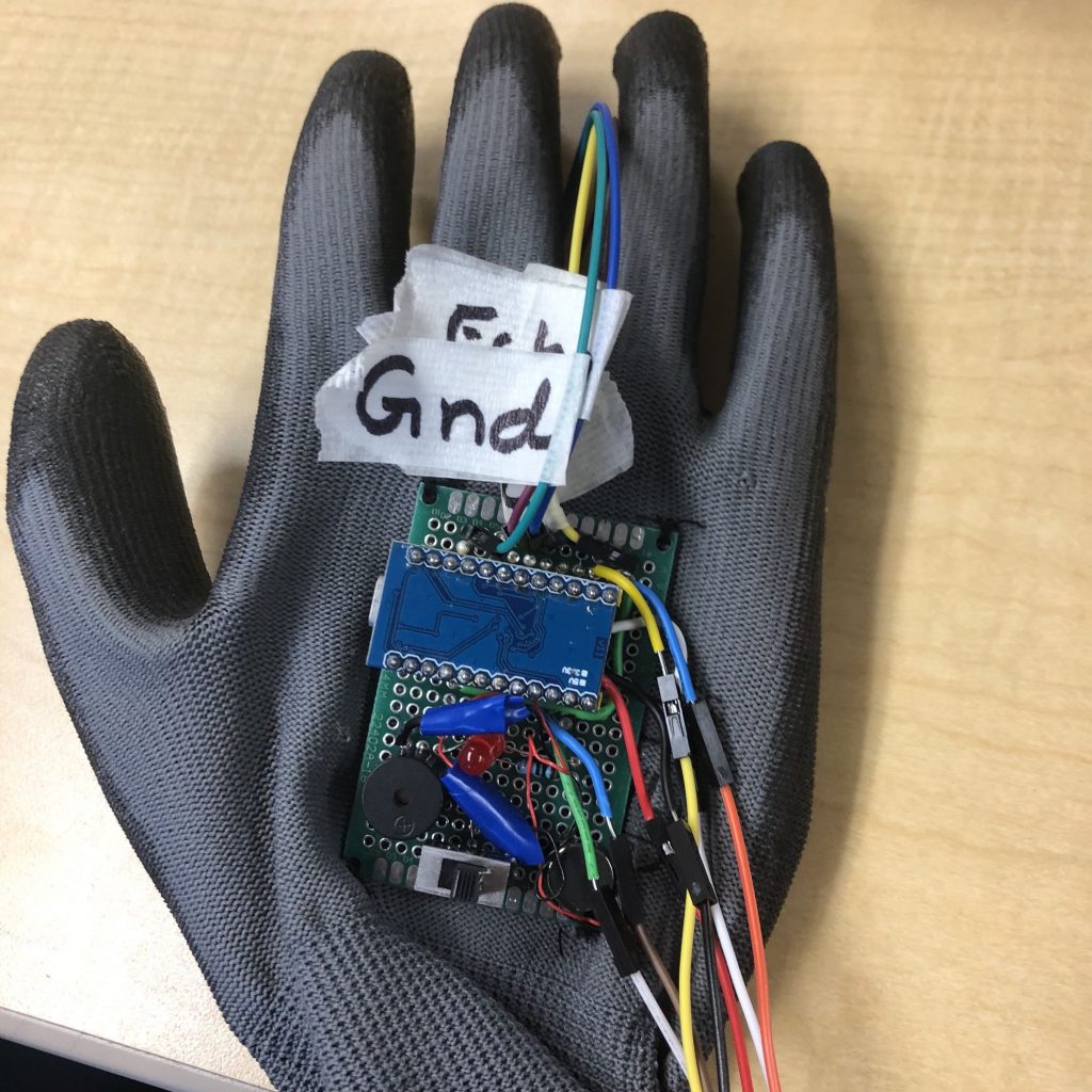
While I was striving to achieve my third milestone, I had to figure out what method I was gonna use to put the circuit on the glove. I started by using hot glue. However, the PCB kept falling off and the hot glue idea was scrapped. Then I had to learn to sew, and this method turned out to be very effective and allowed me to finish the milestone.
My next step is to put the circuit on 3d printed glasses to allow “eyes” for the blind.
Second Milestone
First Milestone
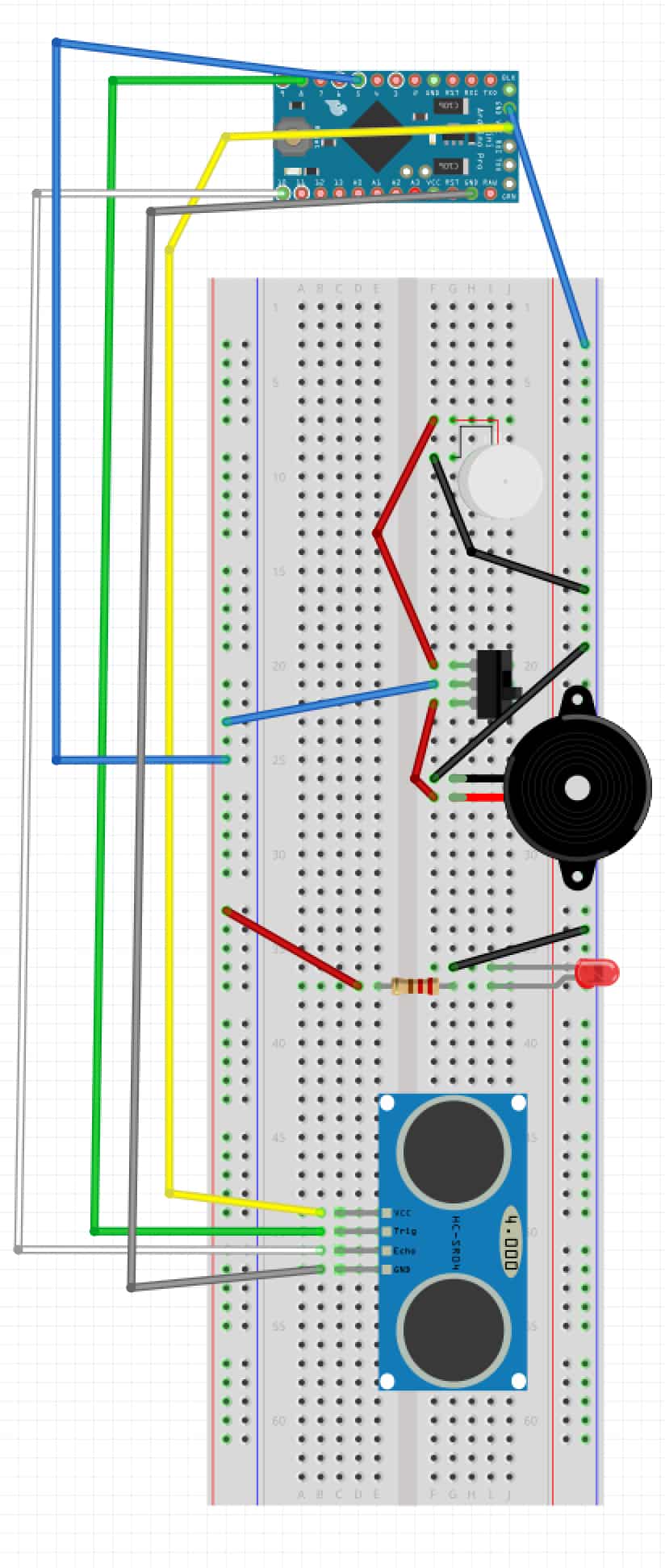
While I was building, there were many roadblocks. First, the switch would not fit in the breadboard. I solved this issue by filing down the three pins. Another issue was the type of arduino was not correct. The project asks for a Arduino Pro Mini, however I had an Arduino Pro Micro Leonardo. This required me to use different pins, causing alterations in the wiring as well as the code. I learnt what serial() in Arduinos do. I also learnt how to connects flipswitches, as well as, how one pin on the Arduino can cause multiple output.
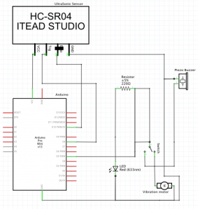
The different components I used include the ultrasonic sensor, led, piezo buzzer, flipswitch, and vibration buzzer. The ultrasonic sensors send out an ultrasonic wave which is bounced back by an object. While this is happening, the crystal oscillator keeps time and multiplies the time for the sound to bounce back divided by 2 by speed. In a sense, its echolocation. The switch moves the circuit between the left and the middle pin or the right and middle pin, allowing there to be a choice between two different circuits. The vibration motor works by rotating a mass which is shifting weight in a circle.
My next goal will be to move everything to a PCB board to make it compact on the glove.