Hi! My name is Amiel, and I am a rising Senior at SAR High School. This is my second year here at BlueStamp, meaning that I have been able to work on a more advanced project this year, using both old and new knowledge. For my starter project, I built a digital multimeter, which is capable of measuring voltage, current, and resistance. I chose it because a multimeter is an essential tool for any engineer creating circuits. It was also very interesting to learn how it can measure each value of the circuit or part. For my main project, I built a robot that has many functions. These include being controlled by a PS2 controller, possessing an autopilot mode in which the robot can detect walls around itself and turn to avoid them, possessing a screen with which to display information, and having a robotic claw that can be controlled manually to mimic a human arm. There is also a Wave Shield that allows the robot to speak to me when I tell it to do so. I chose this because it blends mechanical and electrical engineering, along with computer science and robotics. It has many different components that must all work together seamlessly in order for the robot to function. Read through the following to learn more about what I have accomplished this summer.
Multifunctional Robot
Final Milestone
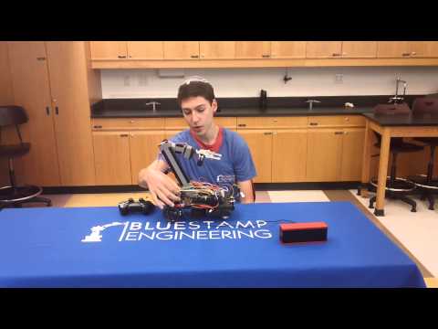
My final milestone is for completing two different modifications. I built a robotic arm out of wood, electrical tape, hot glue, and five non-continuous rotation servos. I also switched my Arduino Uno for an Arduino Mega, which has many more pins. This is important because if I had wanted to run the claw before switching micro controllers, I would have had to disconnect both wheels along with the servo that controls the ultrasonic sensor. Now, I can have all of my components connected at the same time. Then, I used the Arduino Uno to control an Adafruit Wave Shield. I connected the two Arduinos together with several jumper wires so that the Mega can tell the Uno when to talk and what to say. The Wave Shield can convert data stored on an SD card into sound, allowing the robot to talk to me. It tells me what mode it is in, along with what direction it is going.
Here is my final schematic:

Here are my codes:
Code for Arduino Mega: Mega Code
Code for Arduino Uno with Wave Shield: Uno Code
Here are the parts I used and the links to where to get them:
Milestone #2
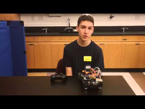
My second milestone is for completing my robot before adding modifications. I connected the wheels to continuous rotation servos, and the servos to the base, via 3D printed motor mounts. These are located on the bottom in the back. I also have casters in the front so that I can steer without interference from frontal wheels, which might produce friction between themselves and the floor. On top, I have an Arduino Uno, in a 3D printed case, connected to two 9V batteries in parallel. The batteries also connect through a voltage regulator to the rest of the components, ensuring that they can only get 5V. I have the Arduino connected to a PS2 controller, which allows me to control the Arduino in manual mode, and then toggle between manual mode and autopilot mode. It is also connected to an OLED, a screen that allows me to display which mode the robot is currently in, and which direction it is turning. Next to the OLED, I have a piezoelectric speaker that makes a beeping noise when I press a button on the PS2 controller. I also have a servo in the front connected to an ultrasonic sensor. When in autopilot mode, the robot will keep going forward until it approaches an obstacle. When the ultrasonic sensor detects an object in front of it by sending out a sound wave and timing it to see how long it takes to get back, thus detecting the distance between the sensor and the obstacle, the Arduino tells the robot to stop. The servo then turns to allow the ultrasonic sensor to scan either side of the robot, detecting which side has a longer distance between the robot and the nearest obstacle. The Arduino then turns in that direction. If neither side is clear, the robot will go backward and turn around.
Milestone #1
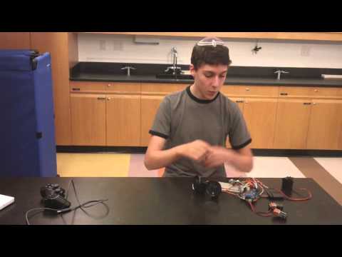
My first milestone is for successfully connecting the PS2 controller, OLED screen, ultrasonic sensor, and servos. The PS2 controller is something that normally controls video games, but can be adapted to control an Arduino project via a receiver wired into the Arduino. The OLED is a screen that can be programmed to make various designs and display text of my choice. I set it to display the status of the servos. The ultrasonic sensor is a small attachment that can detect its distance to the nearest obstacle. It sends out a burst of sound, inaudible to human ears, and records how long it takes to bounce off of the closest object and return to the receiver. Using this, along with the speed of sound, a known number, the Arduino can calculate the distance to the closest obstacle, and react accordingly. The servos are small but powerful motors. They can spin in either direction, and can be told to hold their position, distinguishing them from standard DC motors. I can also control them by pressing buttons on the PS2 controller or by setting them to change direction when the ultrasonic sensor detects a nearby object.
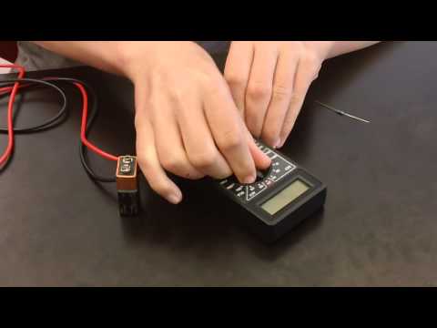
Starter Project: Digital Multimeter
For my starter project, I built the Digital Multimeter, built by Elenco. A multimeter is a device that can measure voltage, current, and resistance, among other parts of a circuit. It has two probes that touch the components of the circuit to be measured, such as a resistor, transistor, battery, or wire. It also has a knob that allows the user to switch between modes and scales. Once the knob is set to the correct setting, the two probes are placed touching the circuit part. The scalar of the measurement is shown on the screen at the top. The multimeter can also measure whether or not two parts of a circuit are connected to each other, making a beeping noise if it registers a connection. The multimeter measures voltage by using a resistor with extremely high resistance to force the current through the circuit and not drop voltage going through the meter. Then, the multimeter can measure the potential difference between the two probes. It measures current by having the probes redirect the current of the circuit across a shunt wire and measure the voltage at each end. Since the resistance of the wire is known, the multimeter can apply Ohm’s Law (V=IR) to find the current of the circuit. To find resistance, the multimeter uses a battery inside its casing to put a given current across the tested resistor and measure the voltage, again using Ohm’s Law to find the resistance.