Automatic Stabilization Gimbal
My project is a stabilization gimbal. A gimbal is a device rotating around a set of axes. This project was being used to stabilize a camera.
Engineer
Shreya M.
Area of Interest
Computer Engineering
School
Saint Francis High Schoool
Grade
Incoming Sophomore
Reflections and Conclusions
Milestone 3
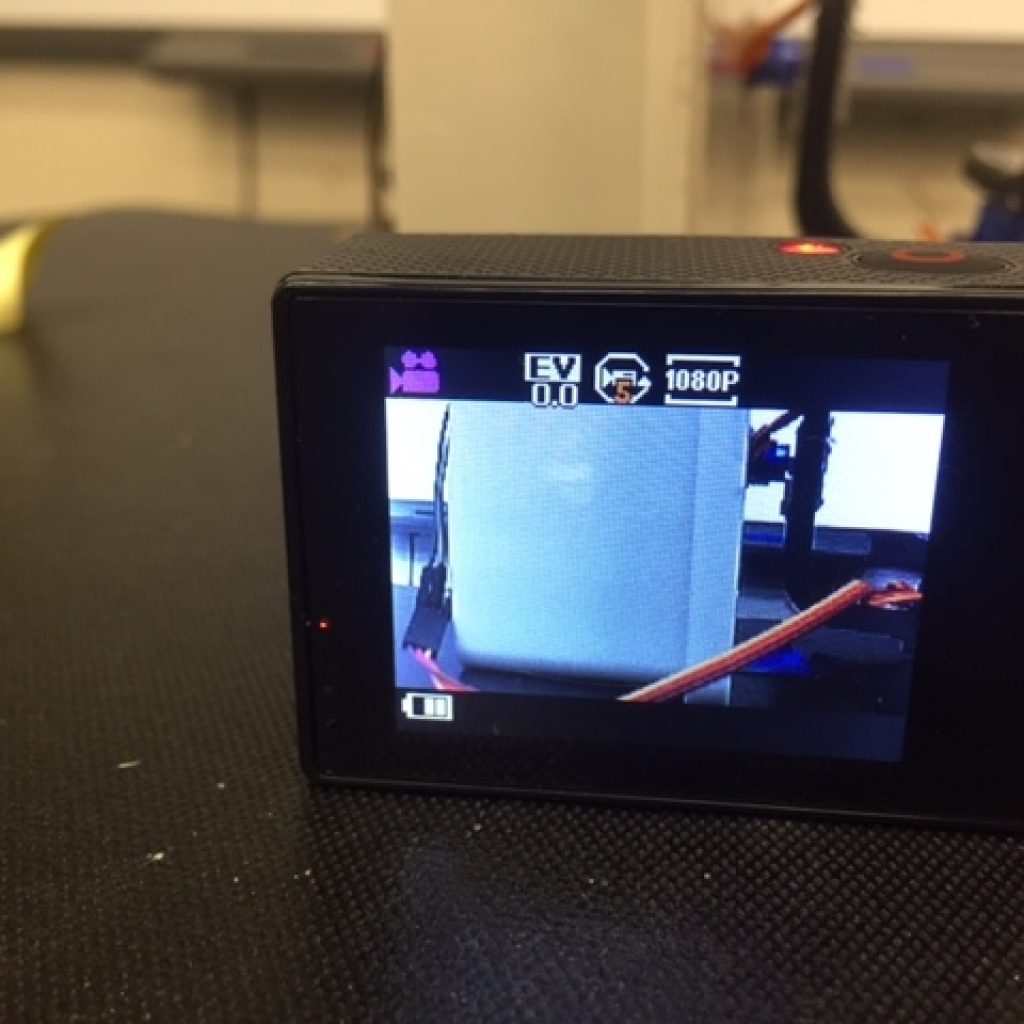
My project is an autonomic stabalization gimbal. This functions as a camera stabilizer. In my third milestone, I assembled all the mechanical parts and I changed all my code, as I realized that my original code for the gimbal was not stabilizing the device properly.
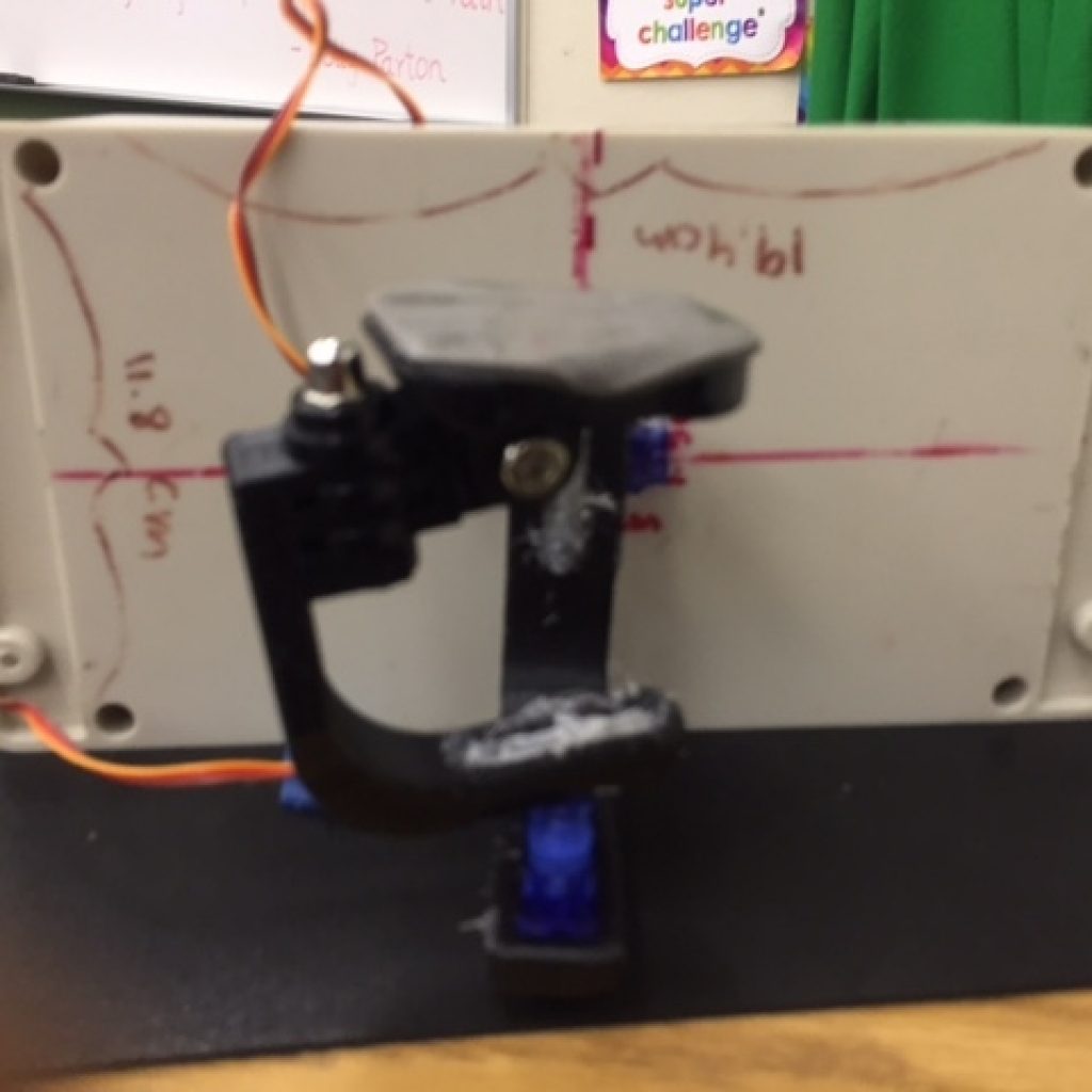
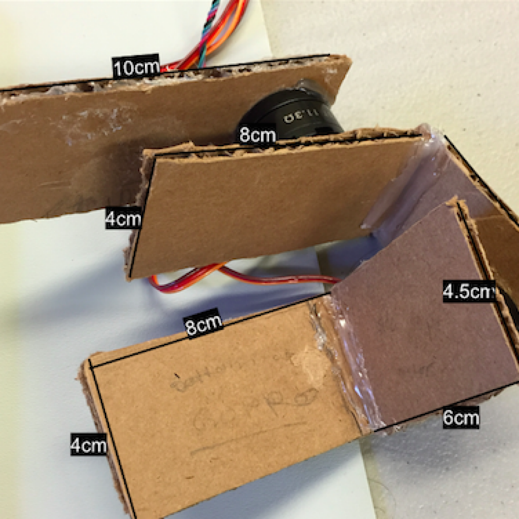
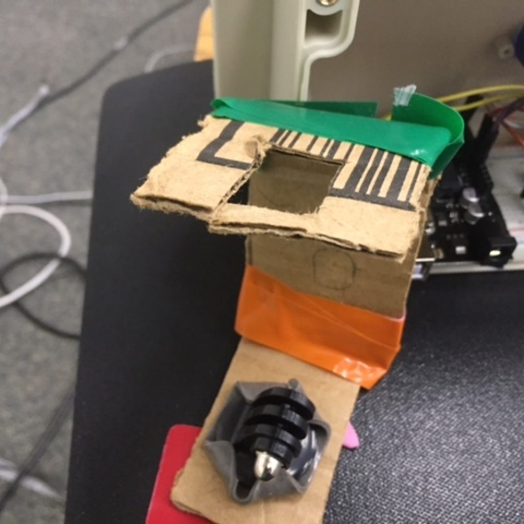
Assembling all my Mechanical Parts
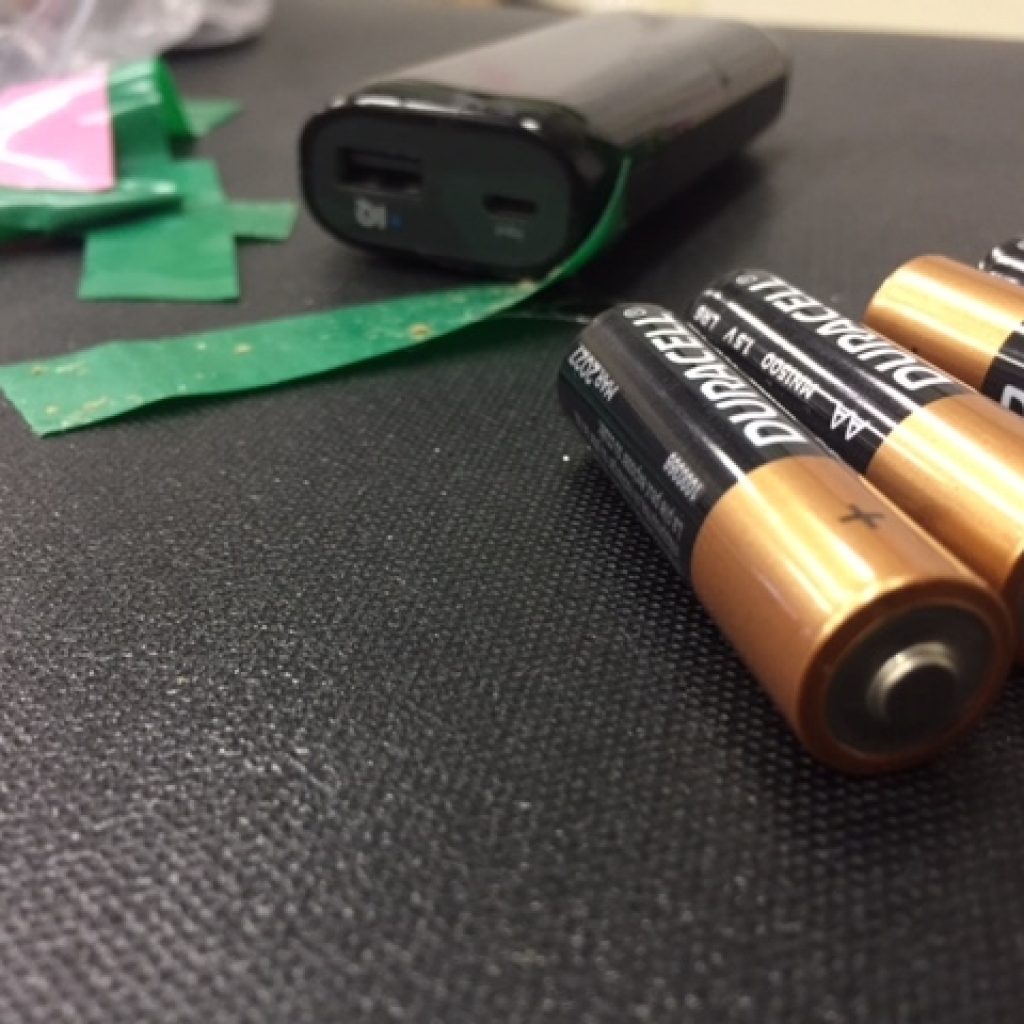
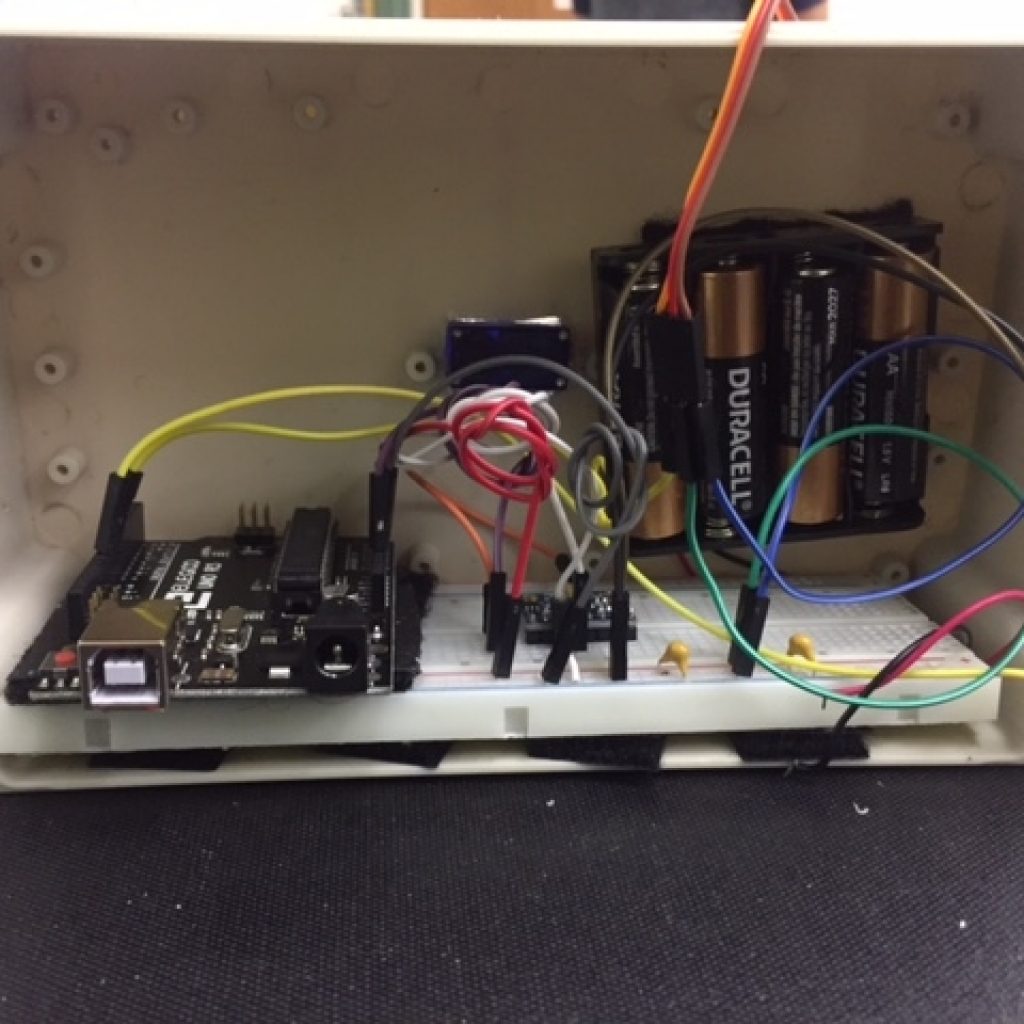
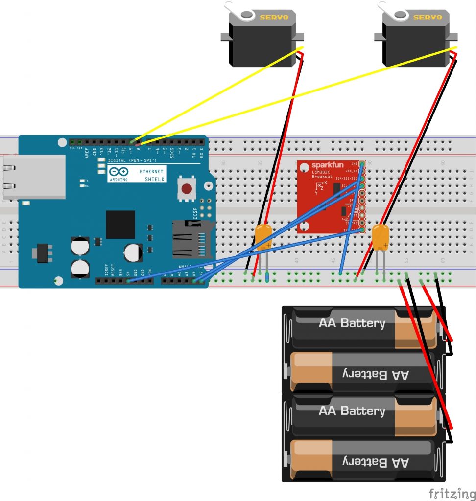
To assemble all my mechanical parts, I spent extensive time CAD modeling and connecting my parts together. Firstly, I drilled a hole in my box, which I then filed to match the size of the servo that would eventually fit into it. Later, I oriented my arms so that the X-axis servo could fit directly in the hole. Then, I 3D-printed my arms. My arms came with a lot of support material that I had to file out so that the servos would fit through the mounting holes. I later hot glued my servos to the arms of my gimbal. I correctly oriented and later mounted my breadboard inside my box. I found out that AA batteries function as a power source that I can use to power my gimbal, which was previously being powered by my computer. By slightly changing the wiring of the breadboard I was using, my gimbal started to work well with the AA batteries.
Changing my Code
My original code was not effectively stabilizing the camera so, I completely changed my code. I added on to my original code, completely scratching some parts I originally used. Firstly, I added a Kalman filter to control sensitivity of my IMU. I had to add this because, the IMU was sensing very faint movement, causing the servos to act erratically. Secondly, I switched from use of the accelerometer to use of the gyroscope. Since my project centers around angular motions of a box, using an accelerometer and a gyroscope would be more efficient to use than just an accelerometer. This is because a gyroscope senses angular movement and working with the accelerometer would increase efficiency of my gimbal. Later, I determined the axes that corresponding to each servo. There are three main axes, yaw pitch and roll, which correspond to the z, y and x axes respectively. Based on the position I mounted the breadboard and my arms, I assigned my servos an axis. After this, I determined an origin or centerpoint for my code. All other coordinates are mapped relative to the origin. Hence, finding the correct origin was vital for the stabilization of my gimbal. Finally, after many hours of trial and error, I found the correct algorithm to counteract the movement of each of the arms. Trial and error helped me formulate the correct number of degrees to counteract movement from the z axis and the y axis.
Challenges I faced + How I overcame them
I faced many challenges. The main challenge I faced was with the calibration and setting the zeros so other points could be mapped to it. Secondly, the correct algorithm to stabilize was difficult to determine. My gyroscope and accelerometer were giving me erratic results for a long period of time, as they were constantly changing. Hence, it took me a lot of trial and error to figure out the correct origin and stabilizing algorithm.
Milestone 2
In my second milestone, I CAD modeled my arms and my box. I also improved my code
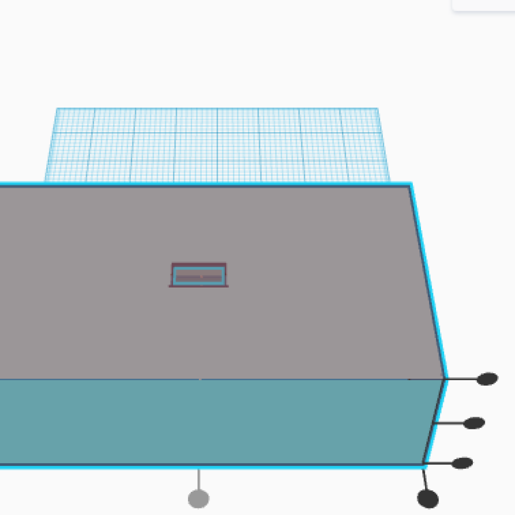
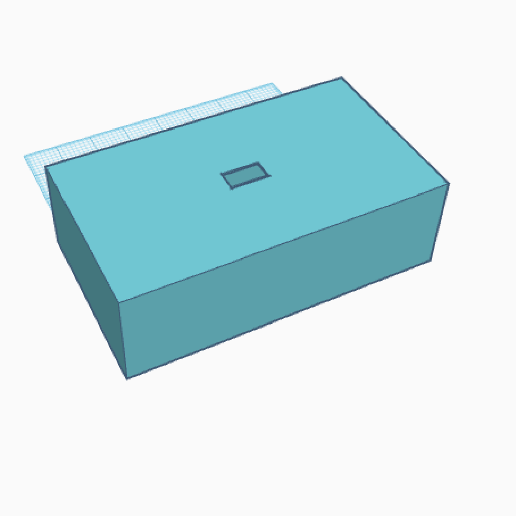
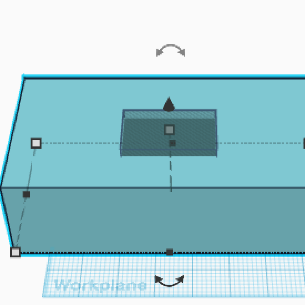
CAD Modeling + Making my arms and my box
To make my arms and my box, I learned how to CAD model. CAD modeling is a way to design and model 2d and 3d objects. I used CAD modeling to help design my arms and box. To design my arms and my box I used a program called TinkerCAD, which I used to export stl files for 3D printing. I used a previous prototype from a website to act as a basis for the design of my arms. Later, I found an alternative to tinkerCAD, a website called onshape. Onshape’s software was more confusing to use, as it was very complicated. I decided to use tinkerCAD in the end and the software proved effective. When designing my arms, I encountered many obstacles, one of which is with 3d modeling itself. The software tinkerCAD did not offer or compile into face drawings (Drawings of each side of the object). Hence, I hand drew my designs for my face drawings.
Coding and adding I2C library.
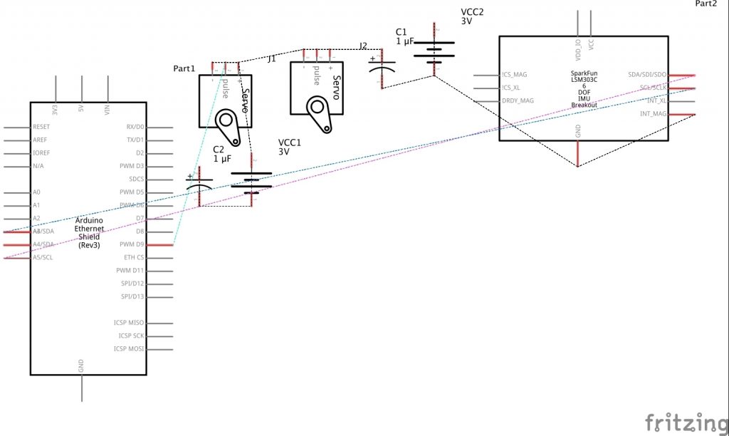
I2c stands for inter integrated circuit. This is used to communicate between peripherals and a microcontroller. In my project, I2c was used to communicate between the arduino and the accelerometer and gyroscope on the IMU.
Other Challenges I faced + How I overcame them
I faced many challenges, some of which, I previously addressed in this milestone. Others included my 3d arms. My arms were printed backwards. Hence, to use them and actually attach them to my device, I had to glue my servo horns onto the prototype gimbal.
Milestone 1
In my first milestone I connected my servos and my IMU to my arduino.
What is a gimbal?
A gimbal is a device that operates by rotation around one or more axes. This is what I used in my project to stabilize my camera.
My project uses an arduino, IMU and a set of servos to achieve a stabilizing effect.
What is an arduino?
An arduino is a microcontroller and acts as the brain of my project. For my project, I used an Arduino Uno as my microcontroller. Arduino Uno has many different parts to help make it function. It uses analog and digital pins. The analog signal varies over the range of many different values. However, digital signal has only two values. Another important part is a ground pin which provides a reference for the voltage. There are also several voltage pins, which are used to supply the correct amount of voltage to anything wired to the arduino.
How it works.
My project uses an IMU to detect acceleration. IMU stands for Inertial Measurement Unit. It consists of an accelerometer and a gyroscope. An accelerometer measures accelerations and a gyroscope measures angular movement. Currently, for my project, I am using an accelerometer. When the accelerometer senses the acceleration, the servos are able to move. The accelerometer has outer plates covering it. Each time the chip experiences a change in acceleration, there is a change in the capacitance. This is how the accelerometer can keep track of changes in acceleration. Each time it senses acceleration, it sends a message to the arduino. The program running arduino interprets this message and sends a signal to the servos to move. In my code, I mapped each value between -900 to 900 to a set of degrees between 0 and 180 degrees.
Major Challenges and how to Solve Them
I had many problems downloading and figuring out which libraries to download for my arduino. I found a library called i2cdevlib, which I had to download to allow for accelerometer movement. However, I was unaware that I also had to download a separate file inside the library for the accelerometer to function properly. This file was especially necessary to control my module, the MPU-6050. I also learned that the accelerometer would fry with the amount of voltage that was being sent to it, as I was sending it 6 volts and it could only handle 3 volts. As a result, I had to replace my IMU with a new one.
Starter Project
My starter project is a weevil eye. The weevil eye is a device that is used to generate light in darkness, kind of like an autonomic version of a flashlight. The weevil eye first uses a photoreceptor, which senses the amount of light present. After the photoreceptor senses the light it sends information to the transistor, which operates similarly to a switch. The transistor sends the electrical signal to the LED lights which brighten then in the presence of darkness. Resistors are placed on the device to make sure that too much current isn’t generated and that the resistor will not overheat.