

Prosthetic Hand – Muscle Research Paper Abstract: The Manipulation of Electromyography to Derive the Necessary Electric Potentials for Natural Finger Movement
The above abstract derives from a research paper I wrote as part of my neuroprosthetic hand independent research project. The experiments I describe were a critical part of my efforts to develop an algorithm for controlling the prosthetic using electromyography. I have since completed a beta version of this algorithm, which I have successfully tested with my prototype hand; ongoing refinements are aimed at improving its robustness to unintentional movement and other sources of noise. The research paper investigates several forearm muscles to determine which is the most consistent predictor of intentional finger movement by analyzing data collected via electromyography. This research is used to 1) pick the optimal forearm muscle to activate the prosthetic and 2) use the data collected for that muscle to program an effective control algorithm capable of autonomously determining a reliable threshold for intentional activation between the baseline and peak voltage potential values outputted from the forearm. In other words, this control algorithm will determine whether the user is intentionally activating the prosthetic, or whether the signals should be attributed to unintentional feedback.
Prosthetic Hand – BWL Continuation: Presentation to Faculty and Administration (38 minutes)

Here is a link to the youtube page in the event that this video does not work: https://youtu.be/eiwhn7_RFec
Prosthetic Hand – BWL Continuation: Writing Motions
An absolutely huge milestone in my prosthetics journey has finally arrived. My hand can write!! The fingers of the prosthetic are making extension and flexion motions producing rapid vertical strokes controlled by action potentials from the body. An increased frequency in these potentials produces voltage differentials across the two receiver electrodes that surpasses my threshold, causing a sequence of flexions and extensions. Each activation datapoint will cause a half second flexion followed by a half second extension. This vertical motion, in addition to the horizontal motion across the page, will allow for curvatures to be made in an identical fashion to biological writing.
Here is a video of me hitting this exciting milestone:

Here is a link to the youtube page in the event that this video does not work: https://youtu.be/kSzCylGhpLw
Prosthetic Hand – BWL Continuation: Electronics Interfacing Biological Activation and Mechanical Motion
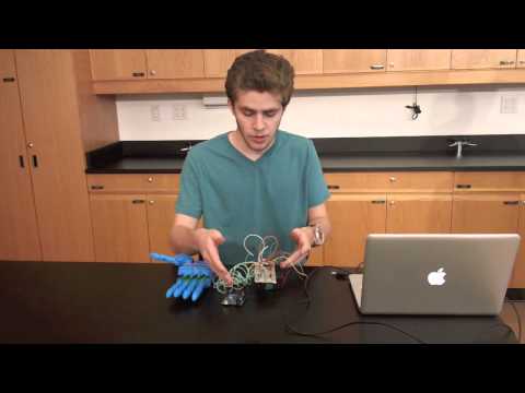
 My prosthetic development is geared towards helping improve writing functionality through implementing near-natural finger movement. The project focuses on integrating neural controls (obtained through the use of an EMG) to provide a biological system of synapse-induced activation. An Arduino processes muscle activity and electrical signals are directed through an H-bridge to spin DC motors in the hand and cause finger flexion and extension.
The EMG detects all levels of electric potential as neurons and muscles fire. These recorded waves are streamed from the EMG to the analog port of the Arduino. These analog waves are then sampled into digital data that can be stored and read by the Arduino. A pre-uploaded program inputs these data points into its algorithm. Each data point is simply a representation of the muscle activity over a period of time. In order for a given datapoint to break the necessary threshold set forth by the uploaded code and be considered biological activation, an increased rate of activity is necessary to create enough potential energy. Upon contracting the flexor carpi ulnaris and breaking the determined threshold, a sequence of digital signals will be sent to an H-bridge, which like a transistor, can direct the flow of current. The H-bridge further deals with the strength of the current, determining from the code how much electrical energy it will allow the fingers to receive. These signals are then sent to the prosthetic fingers, stimulating DC motors to rotate in the appropriate sequence and cause flexion and extension.
Below is a short update video from my first day of successfully interfacing my muscle activity with one prosthetic finger:

Here is a link to the youtube page in the event that this video does not work: https://youtu.be/MSxp3WDom4U
Prosthetic Hand – BWL Continuation: Muscle Experimentation
Natural manual handwriting requires a complex set of stereotypical finger motions that have not been adequately addressed in prostheses at this time. A few current prosthetic devices feature the ability to grip a pencil firmly for writing. However, all of the necessary movements for writing are exerted in areas beyond the hand itself in current models. Amputees instead rely on their elbows and shoulders to produce the fine strokes required to draw lines and curves, significantly limiting their legibility, speed, and endurance. The long-term goal of this project is thus to provide amputees with another area of movement when writing, specifically the fingers. Such a development would allow for more efficient and accurate movements, enabling faster and more naturalistic writing with reduced strain on arm and shoulder muscles. As a first step toward achieving this goal, the proper muscle to interface biological activation with finger movement had to be located.
It was hypothesized that 1) the EMG recording setup would be able to distinguish intentional motor activity from the background level of activity for each muscle tested, but 2) the muscles would vary in how clearly this intentional motor activity could be identified.
An experiment was run where each digit applied a force of 2N, the approximate force needed to generate the pressure used when writing, on a spring scale. The EMG recorded the amplitude of electrical signals at consistent intervals using electrodes placed over a certain muscle area. Using custom code, the processing unit received analog signals from the EMG and translated them into digital potential readings. These readings were recorded and saved to file for later analysis. The entire sequence, including the brief second taken to reach the 2N of force, occurred in a consistent time lapse with multiple trials per finger. Three different muscles were tested in this manner. These three muscles are depicted in the below picture:

I have collected data from a 15-year-old male subject (my brother) via electromyography. This data was used to determine what the baseline average and standard deviations are for the activation potentials, as well as what the peak average and standard deviations are for various circumstances. The EMG data for each trial arrived in the form of an electric potential readout with an initial value around 130ms after recording was initialized, then additional values at regular intervals set to once once every 500ms starting at 1,700ms. To quantify the sensitivity of the EMG to changes in neuromuscular activity, the difference between each reading and the preceding reading was also calculated. The “peak” change in neuromuscular activity was therefore defined as the largest reading-by-reading difference value within a 2000ms window centered around 5,200ms, to account for variation in the subject’s timing. This corresponded to the closest measurement time to the target muscle activity onset time of 5s. For each finger and each muscle site, the reading times were then shifted such that the difference peaks were aligned, as these varied somewhat between trials. The “baseline” epoch was then defined as the readings that preceded the determined peak time point for each trial. Thus, four summary statistics were generated: average baseline EMG reading, average peak EMG reading, average baseline reading-by-reading difference, and average peak difference. Standard deviations were also calculated for each of these measures to quantify their variance. In order to compare the sensitivity of each muscle and finger combination relative to the background level of variation, the signal-to-noise ratio (SNR) was calculated for each. This was accomplished by taking the average peak difference value (i.e. the “signal” of interest) and dividing it by the standard deviation of the corresponding baseline difference value (i.e. the “noise”). The SNR value gives an indication of how easy it will be for a future classifier algorithm to detect a deliberately triggered muscle onset while ignoring random fluctuations in the signal. A larger SNR means unintentional noise is less likely to be classified as an onset (i.e. a false positive) and the detection threshold can be set to a higher value relative to the baseline; the higher this threshold, the less likely the signal is to be missed as an onset (i.e. a false negative).
The results indicated that the muscle identified as the flexor carpi ulnaris (“Muscle 1”) showed the clearest activity peak associated with the onset of the motor task with minimal activity otherwise. The data for all three muscles is shown below:


Prosthetic Hand – Birch Wathen Lenox (BWL) Continuation: Intro
As amazing as BlueStamp was, all great things must end eventually. However, my prosthetics quest would not end with it. After BlueStamp ended, I immediately went to work preparing for the school year ahead. It was at Birch Wathen Lenox of my junior year that I embarked on a year long independent study with Mr. Woody March-Steinman and continued my prosthetics journey. This Advanced Independent Research Study (AIRS) course had a neural investigations focus. This course sought to implement biological activation for a prosthetic system that would emulate natural neural signaling by artificially reproducing the interface between neurons and muscle activity.
Now, the ultimate goal of this entire journey is to produce a prosthetic with writing capabilities. To do so, I needed to find a way to record from muscles in the arm and use data to control vertical writing motion. Initial research required me to understand the natural mechanical motions of a finger (particularly during writing), and to comprehend the “electrical” system of the body that allows for such motions. A mastery of these materials would provide me with answers to questions like: What finger motions am I trying to achieve? What is the biological output I am utilizing to move the fingers? What source will provide this output most effectively?
After having done the research, I found the answers to such questions. The finger motions necessary for writing are both vertical and horizontal motions. However, user movement across a page will provide the horizontal travel, leaving vertical motions left to be produced. These vertical movements are the strokes that must be made by the prosthetic fingers, and therefore must be activated biologically. This activation would be myoelectric signals for the forearm. The input energy for finger motion would need to come from action potentials, which are waves of ion concentration gradients changing along an axon and over the synapses, from neuron to neuron. Two electrodes would pick up the beginning and the end of this impulse traveling, using that data to figure out what the absolute difference of the energy potential is and assigning that a certain value that could be used to move the hand through a certain algorithm. Such activation, though, would not be achieved from the neurons directly, as they are too small and would not provide a strong enough signal using peripheral electrodes. However, muscles act as amplifiers of these neuron signals, as the neural firing transfers at the neuromuscular junction and creates threshold crossings in the muscle, which has a larger surface area to record from. Therefore, a muscle would be an ideal target to provide electrical activation. However, more research revealed to me that all of the muscles specifically intended to move the fingers were closer to the bone. That would not do, as I can only use peripheral recordings without surgically implanting electrodes into my body. Therefore, the next option was to use a peripheral forearm muscle intended for wrist movement. While this does mean that the user would need to activate the prosthetic in a bit of an unconventional manner, the project would not otherwise be effected. The time to begin was approaching.
There were two main steps required to take this mechanical hand and transform it into a true prosthetic. The first step was to find out which forearm muscle would most effectively provide the signal I needed for biological activation. This task would require testing, and thus began my month-long experiment (and subsequent paper) regarding forearm muscles that provide consistent, desirable data for muscle activation. Upon having a muscle to produce readings, the second step consists of building an interface to transfer biological input into mechanical motion. This system of artificially reproducing biological signaling would require the use of more complicated electronics. Three main components would need to be used effectively for a successful sequence: An Electromyograph (EMG) reading signals, an Arduino translating signals and inputing them into preprogrammed code and an H-bride for controlling current and reversing polarity.
**************************************************************************************************************************************************************************************
This is a video of me explaining my three projects at BlueStamp’s parents night and thoroughly discussing and displaying my prosthetic hand, breaking down the three steps I took to get it to where it is now to my fellow BSE engineers and their parents:
Here is a link to the youtube page in the event that this video does not work: http://youtu.be/w6tOH3bciCc
_____________________________________________________________________________________________________________________________________________________________________________
Reflection
I have had a fantastic two years at BlueStamp. That is due mostly to the wonderful and committed instructors that I have had. They have taught me and encouraged me through every step of my amazing experience and, along with Dave and Robin (the co-founders of BSE), have made my time at BlueStamp an incredibly enjoyable one. Being a second year student at BlueStamp, I was eager to share the knowledge I acquired last year with this year’s BSE students. While I did frequently give advice and input, especially when approached, I certainly learned a great deal from my fellow young engineers. The comfortable feeling of entering my “second home” that I experienced last year continued to this year as well. My main project this year centered around mechanical engineering, therefore finally giving me a deeper understanding of each of the three aspects of this profession that I love the most: mechanical engineering (this year), electrical engineering (both years) and programming (mostly last year). Along with the resources, experience and professionalism that BlueStamp offers comes, in my opinion, the most important aspect of the program — the engineers of the future. It was evident to me that all of my fellow BSE students had at least one thing in common — an aspiration for greatness. It is not very often that you can forge a life-long friendship over the course of 6 weeks and I have done so on multiple occasions over the past two years (12 weeks) at BlueStamp.
_____________________________________________________________________________________________________________________________________________________________________________
Prosthetic Hand – Final Blog Post (within BlueStamp)
Within BlueStamp, I have successfully put together a digital watch and gram piano as well as built the mechanical structure of a prosthetic hand with limited yet successful functionality. BlueStamp has been amazing for me this year. Being that I am a returning student, I naturally must try and compare this year’s experience to last year’s. However, they are vastly different in so many respects. Unlike last year, my project this year mostly consisted of mechanical work. As a result of that, most of the problems I encountered this year are problems I have never before faced. Also contrary to last year, I decided to work on a student defined project (SDP) that was not one of the possible options given by BlueStamp. There is one thing, however, that remained the same between the two years — the level of difficulty and amount of time put in. While I did progress in many fields from last year to this one, I look at the similarity in struggle as a testament to my wanting to push myself to work on a project that is mostly outside of my comfort zone.
My main project, the hand, can mostly be broken down into three steps. The first step was 3D printing all of the parts and assembling them without even basic functionality from a mechanical or electrical standpoint. The second part consisted of threading the tendons into the fingers and creating an electrical trigger to control the motors within said fingers. This step therefore implements both the mechanical and electrical aspect of the prosthetic hand. The third and final step revolves around implementing the thumb component and putting the entire hand together in a way that makes it aesthetically pleasing.
My prosthetic hand consists of five fingers, four of which having 3 joints and the thumb having two joints with the ability to rotate its angle as well. The design of the spool within the finger allows for the motor to pull on the tendon around a pulley system, moving the wire parallel to the way the finger bends. The thumb’s rotation requires a servo, which can only rotate up to 180 degrees (or at least the one I am using). When one of my servos shorted out in an attempt to manually reverse its polarity, I decided to bring the servo home and open it up to learn a little bit about the inner workings of this device. What I learned is that the wires from the servo hook up directly to a printed circuit board (PCB) inside and from there, it goes to a direct current (DC) motor which is limited in rotation due to the gears inside. It was therefore evident to me that the reason the current stops at a PCB first is to allow the Arduino to upload code, outputting a Pulse Width Modulated signal (PWM) of variable widths, into the servo and give it instructions on where and how fast to move by using a rotary variable resistor (potentiometer) — which tells the PCB how many degrees from zero the output shaft has rotated. I managed to disconnect the motor from the PCB in the servo and it still worked, teaching me that the PCB must have been the only electrical component effected by my short. So basically, I learned that a servo is just a overly complicated DC motor.
I can rotate the servo using an Arduino Uno and the code that uploads into it. There are three sockets in the servo that attach to the Arduino. There is power, ground, and signal. The signal aspect of the servo is what allows the Arduino code to tell the DC motor inside to turn in either direction by either rotating in the positive or negative degrees, since the servo is unable change directions by alternating the flow of the current (by opening it, I learned this is because it is hooked up to the PCB rather than directly to the motor). My trigger for the rest of the motors can do exactly what the servo cannot. Since the wires are attached directly to the motors, by creating a trigger that alternated the flow of the current, I can shift the direction of the motor — which converts the electrical energy into mechanical energy.
Here is a video of me talking about my overall project and demonstrating it at its fully functional form:
Here is a link to the youtube page in the event that this video does not work: http://youtu.be/MjqysDatVJk
This is my initial code that only controls the servo of the thumb by using an Arduino: https://gist.github.com/RCTank/7dd0e00781c5e84bde12
Here is the Bill of Materials (BOM) list for my prosthetic hand within BlueStamp (note that this list can change later on — higher up — on this website): https://docs.google.com/spreadsheets/d/1OFBBSrXLsQUtT583zTGsqwGYliZUhkTHyp3Yrvd3dYg/edit?usp=sharing
Here are the electrical schematics for the initial phase of my project within BlueStamp, where five DC motors are powered by an electrical trigger and one servo is powered by an Arduino Uno:


Prosthetic Hand – Second Milestone
My second milestone proved to be very challenging yet productive in the overall scheme of my project. I have accomplished the majority of my mechanical work in the weeks leading up to this milestone. I threaded the tendons (fishing wire) through the finger structure, placed the motors into their holsters, created an electrical trigger for the motors, and designed the schematics for said trigger. While these steps might not seem too challenging, and I did not anticipate them to be when I began, they certainly require a lot of patience and determination.
My fingers use a pulley system in which the fishing wire wraps around the spool, which is around the motor axle, and goes down and around grooved ball bearings and into the different sides of the finger. The tendon wraps around two of these pulley systems and then reconnect at the finger tip. A spring is used to increase slack and relieve the tension on the wire as it goes through the tensioners. The fingers are set up in this way because the motor rotates perpendicular to the push and pull of the tendons. Therefore, the spool allows the wire to be fed into a pulley system that moves parallel with this process.
The electrical trigger I designed for my fingers is another huge part of my project within the realm of BlueStamp. While I will be using an Arduino to control the hand down the road, I built this trigger for both the learning experience as well as showing that my fingers can move at its most basic form. I designed two triggers in this process. The first one hooks up voltage to one switch and ground to the to the other and then connected both switches to both sides of the motor, allowing me to turn the motor in either direction by turning both switches one way or the other. Then, I decided that it would be more efficient if I found a way to only need to hit one switch to turn the motor one way and one to turn it the other. Therefore, I used two double pole, single throw switches (DPST), which means that the circuit can be completed through the switch at two poles but they both attach simultaneously. They allow the current to flow through one of the the poles, into the motor and out the other side where it can flow back through the other pole of the same switch. Then, to control the other switch, the poles of the two respective switches are attached to the opposite pole to allow for a reverse of the previous current flow, changing the direction of the motor. Then, I attached the motors in parallel to each other, the positive pole to all the positives and the negative pole to all the negatives for each motor, to allow all the motors to use the 6 volts from the battery source.
In the process, I ran into many problems with my hand structure and a few problems with my trigger as well. The tendons kept unwrapping from the spool and the overall construction was a rather long and, at times, tedious process. At one point during the process of making an efficient and functional electrical trigger, the two ends of both of my switches switch were not isolated; rather, they made an electrical connection. That is significant because the two ends of a switch should only have a connection when the bridge is manually closed (by pressing the button). Therefore, by not isolating the two ends, I was allowing current flow directly into the battery. This shorted out my circuit and burned the battery. Also, for the battery, I did not have a battery case that allowed for 4 AA batteries and so I used two 3 AA battery cases and attached the two in series with 3 batteries in one and 1 in the other.
Here is a video of me discussing my experience with electrical circuitry and the way my hand works to this point:
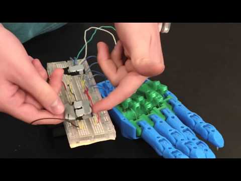
Here is a link to the youtube page in the event that this video does not work: http://youtu.be/dn2QOtETFqg
Prosthetic Hand – First Milestone
For my first milestone, I have assembled the major components of a prosthetic hand without attachment or current functionality. This milestone, however is one of great importance to my project. Aside from completing a ton of hard mechanical work and working through a multitude of obstacles, reaching this milestone allows me to observe the individual parts and their components. This will prove to be critical, as after I have put the hand together per following Joel’s instruction, I will need to manipulate the 3D components and lock some of them in place as well as allow them to move slightly differently. This is because ultimately, the goal of my project, within my limited time at BlueStamp, is to create the structure of a hand that will eventually be able to efficiently write with a pen or pencil.
My prosthetic hand parts feature four fingers that consist of three joints each and then one finger (the thumb) with two joints. All of the parts are 3D printed and put together via mostly screws, ball bearings, and dowels. The thumb has a servo in it to allow for side rotation across the base of the hand. There is the main structure, featuring the palm and back of the hand with room in the middle to place the motors which will ultimately be the direct source of control. The ball bearings, with dowels in them, serve as joints in all of the fingers.
I ran into many difficulties in my first real mechanical engineering experience. Working with 3D printing can be frustrating when extreme precision is necessary because printing even the smallest part, if it require high resolution, can take twice as long. Also, many of the 3D printed parts used had issues. The fit was often too tight and the design was slightly altered in an attempt to turn a model into reality due to the lack of incredible precision when working with a 3D printer. The ball bearings more than anything else required much attention. Fitting the 3mm dowels through even smaller holes required the use of many power tools, a hammer, and many hours.
Here is a video of me discussing my first mechanical engineering experience and the various pieces of my prosthetic hand:
Here is a link to the youtube page in the event that this video does not work: http://youtu.be/xvUFjwIGn0k

This work is licensed under a Creative Commons Attribution-NonCommercial-ShareAlike 4.0 International License.