
My name is Sanjana K, and I am a rising junior at Homestead High School. My starter project was a TV-B-Gone, whose tutorial is found here, and my main project was a 3D printed robotic arm. The tutorial I used to build the arm is found here.
Reflection:
During my time at BlueStamp, I learned a lot of new things whether it be about engineering or myself. I was able to gain more exposure to different types of engineering than what I had before and enjoyed doing all of them. I really liked electrical engineering because it was cool to learn how current moves through the circuit and how the amount of voltage a circuit gets affects its function. Although I didn’t do much of it in the camp, mechanical engineering also spiked my interest because I like building things and knowing how it works. I also expanded on my software engineering knowledge. Throughout the camp, I had to do a lot of problem solving and I found out that a lot of the problems I had were really small. A lot of the problems were caused by wires, especially ground wires, that were not plugged in properly so this taught me to look closer at all the connections in the project. The problems I dealt with tested my perseverance by forcing me to keep trying to figure out a solution for multiple days without giving up.

All the code I made can be found on Google Drive or GitHub
Electronics Schematic:


The parts for the hand were found here: http://theroboarm.com/overview.html.
Final Milestone:
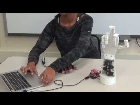
For my final milestone, I had to make the robotic hand mimic the glove wirelessly. To do this, I made the glove have separate code in a separate Arduino UNO. The glove gets the analog signals from the flex sensors and sends that information through XBee modules. XBee modules allow information to be sent wirelessly from one XBee to the other. To make the XBees work with the Arduino, I had to first configure them so they could communicate with each other. Next, I connected them to the two Arduinos using XBee shields(makes the XBee connected to the Arduino). The analog signals are then sent from the glove XBee to the hand XBee with a number added to the front of the signal number so the hand can know which finger to move. To view the code used in the glove’s Arduino, click this link. I also soldered wires for power and ground to a pcb and connected the non-soldered ends of the wire to the servo. The servos are powered separately with a 5V power supply because they need 4-6 volts or they will not be able to work properly.
Since I was able to finish the project early, I worked on improving it and wrote two different programs to make the hand do different things. To improve the grip of the hand, I painted a clear, rubber coating on the pads of the fingers and on the palm. The coating greatly improved the grip of the hand allowing it to hold a wider variety of things and prevented objects from slipping out of the hand. The first extra program I wrote for the hand finger spelled in sign language. Due to the fingers not having much range of motion and the wrist not being actuated, I could only code for 13 of the letters. To figure out where each finger should be for each letter, I made a table that you can view here. The other program I wrote makes the hand move in a way that represents morse code. The “.” was represented by the finger bending half way, the “-” was represented by the finger fully bending, and the “ “ was represented by the hand staying flexed. To organize the data, I made a table again and you can view it here.
Milestone #1:
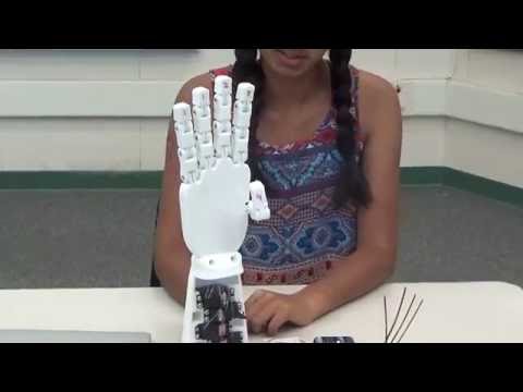

For my first milestone, I had to make all the fingers move by bending the flex sensors connected to a breadboard. The hand itself is made up of 3D printed components that are connected to each other with bolts and locking nuts. Fishing line is used in place of the tendons inside the hand which are responsible for moving individual fingers. The fishing line is run through the fingers and palm and ends at the forearm in the front of the fingers and the back. The lines that run through the front of the fingers make the bend in the flexing motion. The lines that run through the back of the fingers make the fingers straighten or extend. To control the motion of the fingers, servos are installed in the forearm and they move to pull one of the strings to make the fingers flex or extend. The flex sensors are basically long resistors, whose resistance increases when it undergoes stress(the bending of the sensors). The Arduino senses the change in resistance and when it is in a certain range it makes the servo move and therefore moves the fingers. When I bend the flex sensor closest to the Arduino, the pinky finger and the ring finger both move down in a way similar to when you bend those to fingers. The flex sensor next to it controls the the middle finger. The last 2 control the pointer and thumb fingers. My next milestone is to make the flex sensors into a glove and control the hand robotic hand wirelessly.
Starter Project:
The starter project I chose to do was the TV-B-Gone, which is a small universal remote that turns off TVs. To turn off a TV using the TV-B-Gone, one must press the button to start the code to make the IR LED lights turn on. When the button is pressed, the reset code is activated causing the code in the microcontroller to start. All the code that runs the remote is located inside the microcontroller which is connected attached to the CPU through the 8-pin IC socket. This allows the code to be changed if needed. The microcontroller’s code tells the oscillator and the capacitor what electric signals to send. The electric signals are sent to the transistors that turn either on or off and in turn change the IR LED lights from on to off or vice versa. To control the voltage in the circuit, there are 2 resistors, the resistors make sure the voltage isn’t too low or too high to keep the circuit running. The IR LED lights are invisible to the human eye, so there is another LED light that blinks to show that the circuit is working.