
My name is Rye and I am a rising junior at Greenwich High School. This summer, I built the SparkFun Gram Piano and a 3-joint robotic arm (Here’s an example of a similar project). I chose to build the robotic arm because I thought it was an interesting combination of coding and mechanical engineering. I also thought it was a cool project that would be challenging and impressive. Although I am a musician and I considered doing a music-related project, I decided on the robotic arm because I figured that it was more versatile and had more interesting real-world applications.
Reflection
I very much enjoyed my time at BlueStamp. I learned a lot more about simple programming, electronic components, circuitry, problem-solving, debugging, and other skills than I would have in any course at school. It was a challenging course and I had to learn a lot on my own, but I never found myself bored. Watching my project materialize and develop was incredibly satisfying, even during the difficult parts, and I hope to continue making projects like the one I did here after the program ends. Being here at BlueStamp has helped me find what I am good at and what I enjoy. For instance, before BlueStamp, I had never done or even considered doing any sort of computer programming. Now that I have been exposed to it, I plan to continue learning how to program throughout high school. I found that many other students dreaded writing code to make their projects work, but personally, it was my favorite part. I found that watching code on my computer bring life to something was fascinating to me, even when it was something as simple as turning a servo motor. BlueStamp also helped me learn how to think and solve problems independently. Before BlueStamp, I considered myself a problem-solver, but I was surprised at the beginning of the program how many times I found myself needing to ask for help. As the program progressed, I would encounter problems and try to fix them on my own. By the last week or two, I was figuring out most things for myself and I didn’t need instruction nearly as much. I noticed that I would brainstorm possible causes, fixes, and ways to locate problems within my project without even thinking twice. Overall, I feel that being at BlueStamp was an incredibly worthwhile and rewarding experience.
Table of Contents
Final Milestone
Final Documentation
Second Milestone
First Milestone
Starter Project
Final Project
My final project is a 3-Joint Robotic Arm that is controlled with key presses on a keyboard. There are a total of 4 servos, each one being controlled with two keys. Running some separate code I wrote in Processing (a java-based piece of software that can communicate with the Arduino) allows for each servo to be moved up or down with keys. Processing also displays the angle of each servo as well as whether or not the gripper servo is currently open or closed. Below is my source code for my final project, my bill of materials, my build plan, and my CAD. My source code includes both the code for Processing and for the Arduino, and my CAD was created in an online CAD system called OnShape.

An image of my CAD:

Final Milestone
By my final milestone, I had got all of the servos working, connected all of the mechanical parts of the arm together, and programmed the Arduino to move the servos when I press keys on the keyboard. For the mechanical parts, I simply cut a long piece of aluminum to the dimensions I wanted and drilled holes in both the aluminum and the servo arms. This allowed me to mount the aluminum pieces onto the servos with screws. I then super glued the backs of each servo to another aluminum piece so that the pieces would form a 3-jointed arm. To control the arm’s movement with my keyboard, I wrote some code in a separate IDE called Processing, which is Java-based and communicates with the Arduino via the serial port. Processing, unlike Arduino, also has the ability to detect key presses on the keyboard. When a key is pressed, Processing detects which key is pressed and sends the appropriate key to the Arduino. The Arduino either increases or decreases the angle of the servo that the key corresponds to. For example, for the first servo, the “a” key would increase the angle and the “s” key would decrease it.
This was probably the biggest software challenge of the project for me. Getting the Arduino board and the Processing code to work together took longer than I expected. Originally, I tried running my Processing program and then uploading the Arduino code to the board. Each time, the Arduino failed to upload and the board would not work with Processing. At the time, I didn’t realize that both applications were trying to communicate with the board via the same serial port. Eventually, I figured out that I had to upload the Arduino code to the board, close out of the Arduino IDE (thereby freeing up the serial port), and then run my Processing code. After this, the Arduino board and Processing would communicate, but not exactly how I had intended. For my first attempt at controlling the servos with my keyboard, my Processing code sent an angle value to the Arduino and the Arduino was supposed to read that value and move the servo accordingly. However, I later learned that the Arduino reads incoming serial data one byte at a time, meaning that it would read an incoming angle value like “180” as the angle “1”, then the angle “8”, then the angle “0”. This caused my servos to twitch and move uncontrollably. I fixed this by using Processing to only send a single key to the Arduino. The Arduino could read a single key at a time and tell which servo to move and whether or not to move it up or down.
Second Milestone
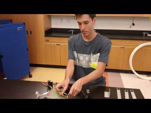
The second milestone I completed when making my robotic arm was connecting four servos and four potentiometers to the Arduino and getting them all to work properly. This step was similar to my first milestone, but had the additional challenge of providing adequate power to each servo so that they could all work at once. In my first milestone, I powered the servo directly from the Arduino’s power supply. However, the Arduino could not power 4 servos at once, so I decided to use an external power source in the form of a DC wall adapter. At first, the wall adapter was not providing power to the breadboard, and I realized that the wires I attached to the adapter were loose. Eventually, I ended up cutting the end off of the wire on the power supply and using alligator clips to attach the power and ground wires directly to the breadboard’s power rails. After this, I took the simple code I used in my first milestone and replicated it so that it would work with four servos, and my second milestone was completed. Below is a schematic for the second milestone of my robotic arm.

Here is my source code for the second milestone (NOTE: This is not the same as my final source code):
A larger version of my schematic can be found below.
First Milestone
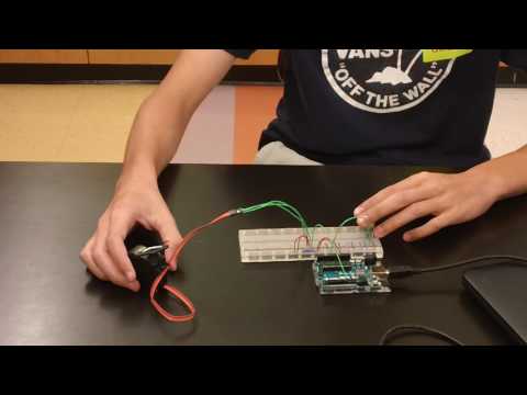
The first milestone in creating my robotic arm was connecting one potentiometer and one servo to the Arduino so that the servo moves when the potentiometer is turned. One of the obstacles I had to overcome when completing this milestone was an uncontrollable servo twitch. Whenever I would plug the servo into the 5V power supply on the Arduino and a PWM pin, the servo would twitch and turn uncontrollably. Turning the potentiometer had no effect on the servo’s position. I fixed this by testing each part of my circuit individually. I tested the servo alone by writing a simple code that told it to move back and forth. This worked fine, so I moved on to the potentiometer. I wrote another simple script that read the value of a connected potentiometer from 0-1023. This also worked fine. Finally, after rewriting the code I used to combine both the servo and the potentiometer, they worked together as expected. Below is a schematic for the first milestone of my robotic arm.

Here is my source code for the first milestone (NOTE: This is not the same as my final source code):
A larger version of my schematic can be found below.
Starter Project
For my starter project, I built the SparkFun Gram Piano. I chose this project because I like listening to and making music. While making this project, I learned a lot about soldering and basic electrical components, such as resistors, capacitors, and potentiometers. I also learned about analog to digital conversion and how to use a multimeter.
I encountered a few problems when making this project. The first was that the piano would not play properly when I pressed a key. Sometimes it would play a note, sometimes it would play nothing, and sometimes it would play a very buzzy and unclear note. I fixed this using a multimeter. I checked the resistance values of each resistor connected to a key to see if they remained constant. If they didn’t, I knew that there was a connection problem and I had to resolder. After fixing a few of these, I noticed that the keys would still only play about half of the time. Additionally, the button on the piano that was supposed to play a preprogrammed set of notes would sometimes play nothing at all. This led me to conclude that there was a problem with the speaker. After resoldering the speaker to the PCB, the piano worked great.
The piano works using the concept of capacitive touch. At its most basic level, this means that when a key is pressed, a circuit is completed. The microcontroller on the PCB has a send and receive pin, and it records the time it takes for the receive pin to change to the same state as the send pin. By pressing one of the keys and completing the circuit, the time it takes for the receive pin to change is increased. The microcontroller detects this, and knows which note that key corresponds to. The potentiometer controls which octave the notes are played at. By causing different amounts of resistance depending on how much the knob is turned, the potentiometer also causes a slight drop in voltage. The microcontroller recognizes this, and converts the potentiometer’s analog input into a digital one by dividing the range of input values into three equal sections. These three sections correspond to three different octaves. Finally, the button on the piano tells the microcontroller to play a preprogrammed set of notes.