RC Hovercraft
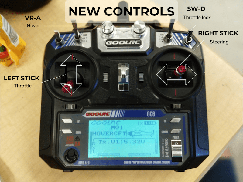
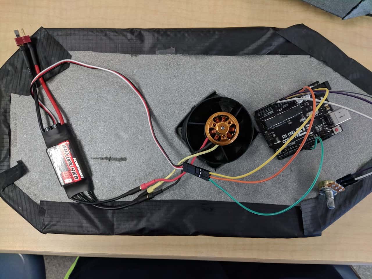
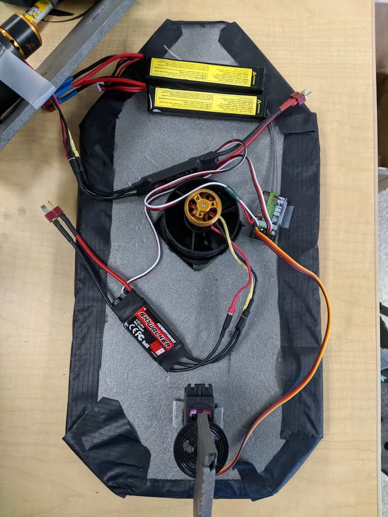
A hovercraft is a vehicle that floats above the ground on a cushion of air; this cushion is provided by a fan blowing downwards and a flexible skirt used to direct the air. My RC hovercraft uses two brushless DC motors, a servo, an Arduino Uno, and two 1000 mAh batteries.
Engineer
Ryan S.
Area of Interest
Computer Engineering
School
Cupertino High School
Grade
Incoming Junior
Reflection
Final Milestone
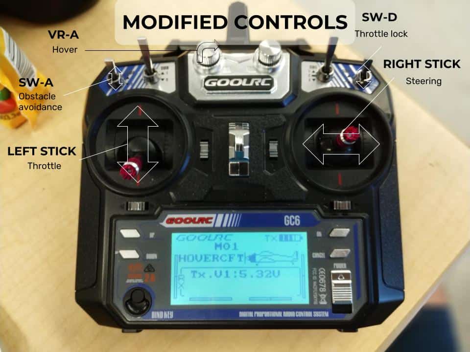
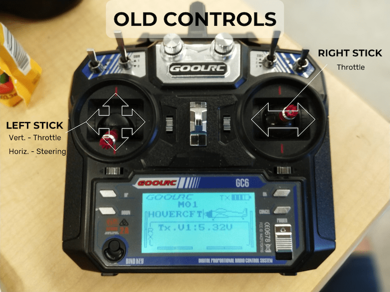
Modifications | Obstacle avoidance

#include <EnableInterrupt.h>
#include <Servo.h>
/*Libraries that are required for the code to run.
 *NOTE: The EnableIntrrupt is not included with Arduino, you will need to download it
 *manually*/
//Defining constants and variables
Servo esc;
Servo servo;

#define SERIAL_PORT_SPEED 9600
#define RC_NUM_CHANNELS  3

bool hasRun = false;

const int trigPin = 10;
const int echoPin = 11;
long duration;
long distance;

int runCount = 0;
int count = 0;
/*
 * CH1 SWITCH
 * CH2 STEERING
 * CH3 THROTTLE
 */
#define RC_CH1  0
#define RC_CH2  1
#define RC_CH3  2

#define RC_CH1_INPUT  A5
#define RC_CH2_INPUT  A1
#define RC_CH3_INPUT  A0

uint16_t rc_values[RC_NUM_CHANNELS];
uint32_t rc_start[RC_NUM_CHANNELS];
volatile uint16_t rc_shared[RC_NUM_CHANNELS];

void rc_read_values() {
  //reads values from RC channels
  noInterrupts();
  memcpy(rc_values, (const void *)rc_shared, sizeof(rc_shared));
  interrupts();
}

void calc_input(uint8_t channel, uint8_t input_pin) {
   //Calculates the duration of each pulse from the reciever
  if (digitalRead(input_pin) == HIGH) {
    rc_start[channel] = micros();
  } else {
    uint16_t rc_compare = (uint16_t)(micros() - rc_start[channel]);
    rc_shared[channel] = rc_compare;
  }
}

void calc_ch1() { calc_input(RC_CH1, RC_CH1_INPUT); }
void calc_ch2() { calc_input(RC_CH2, RC_CH2_INPUT); }
void calc_ch3() { calc_input(RC_CH3, RC_CH3_INPUT); }

void setup() {
  //Initializes serial port and tells Arduino which pins are connected to what
  Serial.begin(SERIAL_PORT_SPEED);

  pinMode(RC_CH1_INPUT, INPUT);
  pinMode(RC_CH2_INPUT, INPUT);
  pinMode(RC_CH3_INPUT, INPUT);

  enableInterrupt(RC_CH1_INPUT, calc_ch1, CHANGE);
  enableInterrupt(RC_CH2_INPUT, calc_ch2, CHANGE);
  enableInterrupt(RC_CH3_INPUT, calc_ch3, CHANGE);

  pinMode(trigPin, OUTPUT);
  pinMode(echoPin, INPUT);

  servo.attach(9);
  esc.attach(13);
}

void loop() {
  rc_read_values();
  int toggle;
  int steering;
  int hover;

  toggle = rc_values[RC_CH1]; // min 992, max 1984
  steering = rc_values[RC_CH2]; // min 996, mid 1488, max 1988
  hover = rc_values[RC_CH3]; // min 996 max 2000

  if (steering == 0){
    steering = 92;
  }

  steering = map(steering, 996, 1988, 47, 137);
  hover = map(hover, 996, 2000, 1000, 2000);

  //Outputs data to the serial monitor for easier debugging
  Serial.print("Switch: "); Serial.print(toggle); Serial.print("\t");
  Serial.print("Servo :"); Serial.print(steering); Serial.print("\t");
  Serial.print("Throttle: "); Serial.print(hover); Serial.print("\t");
  Serial.print("Distance :"); Serial.print(distance); Serial.println("\t");
  Serial.print("runCount: "); Serial.print(runCount); //Serial.print("\t");
  Serial.print("Distance :"); Serial.print(distance); //Serial.println("\t");
  Serial.print("HasTurned: "); Serial.print(hasRun); Serial.println("\t");
  if (toggle <= 1500) {
    //Obstacle avoidance OFF
    esc.write(hover);
    servo.write(steering);
  } else {
    //Obstacle avoidance ON
    digitalWrite(trigPin, LOW);
    delayMicroseconds(2);
    digitalWrite(trigPin, HIGH);
    delayMicroseconds(10);
    digitalWrite(trigPin, LOW);
    duration = pulseIn(echoPin, HIGH);
    distance = duration * 0.034/2;

    if (distance <= 60) {
      runCount = 0;
      count = count + 1;
      if (count > 5 && hasRun == false) {
        count = 0;

        Serial.println("TURN");
        hasRun = true;
        servo.write(47);
        esc.write(1000);
        delay(1500);
        esc.write(1250);
        delay(3000);
      } else {
        esc.write(hover);
        servo.write (steering);
      }
    } else if (runCount > 10) {
      hasRun = false;
      esc.write(hover);
      servo.write (steering);
    } else {
      runCount = runCount + 1;
      esc.write(hover);
      servo.write (steering);
    }
  }
}
Third Milestone
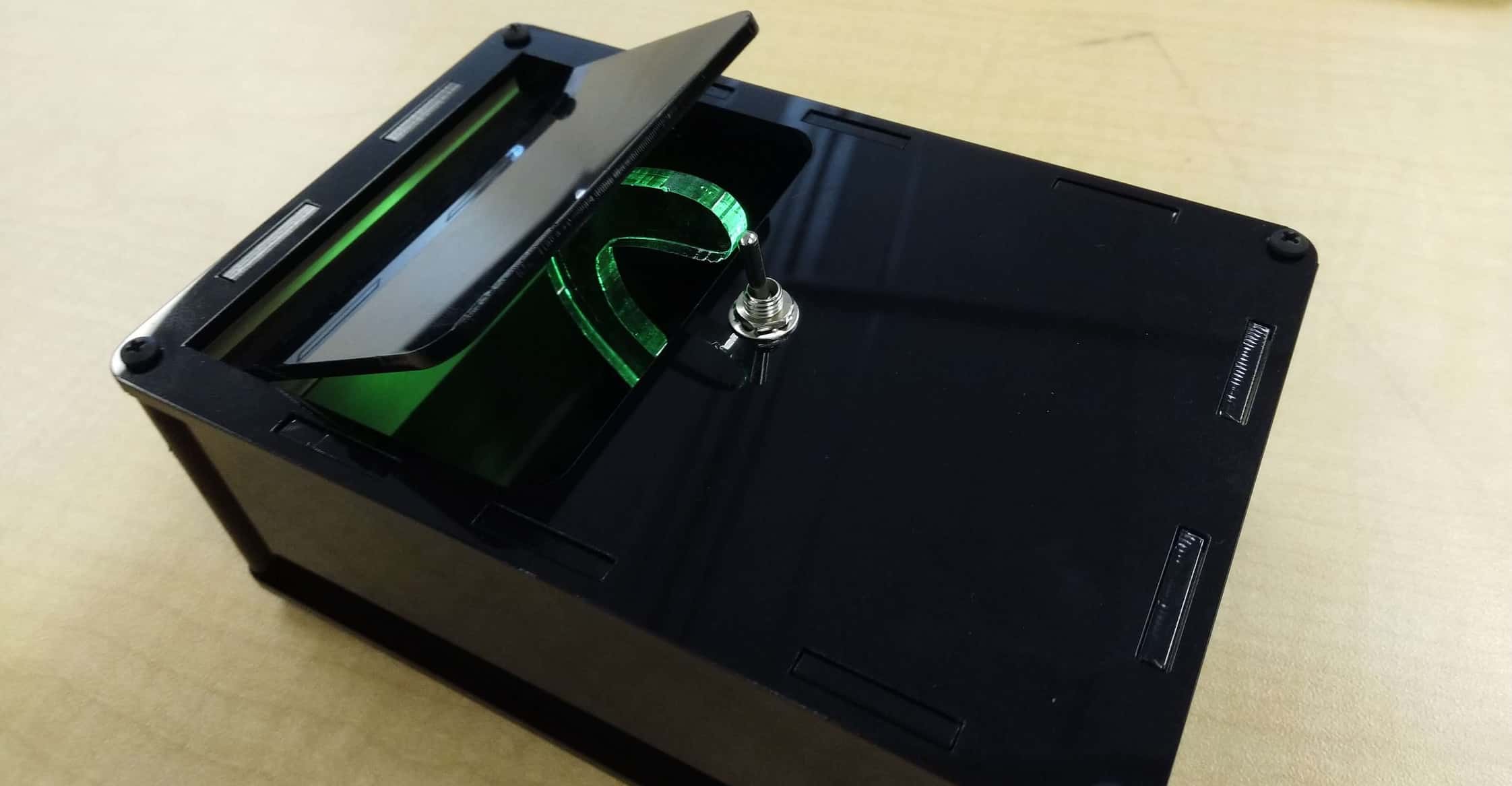
Finishing Touches
Second Milestone
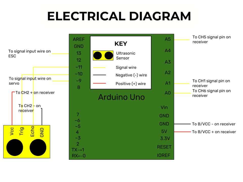
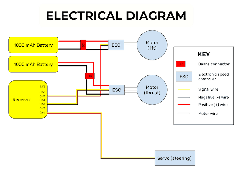
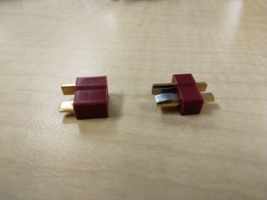
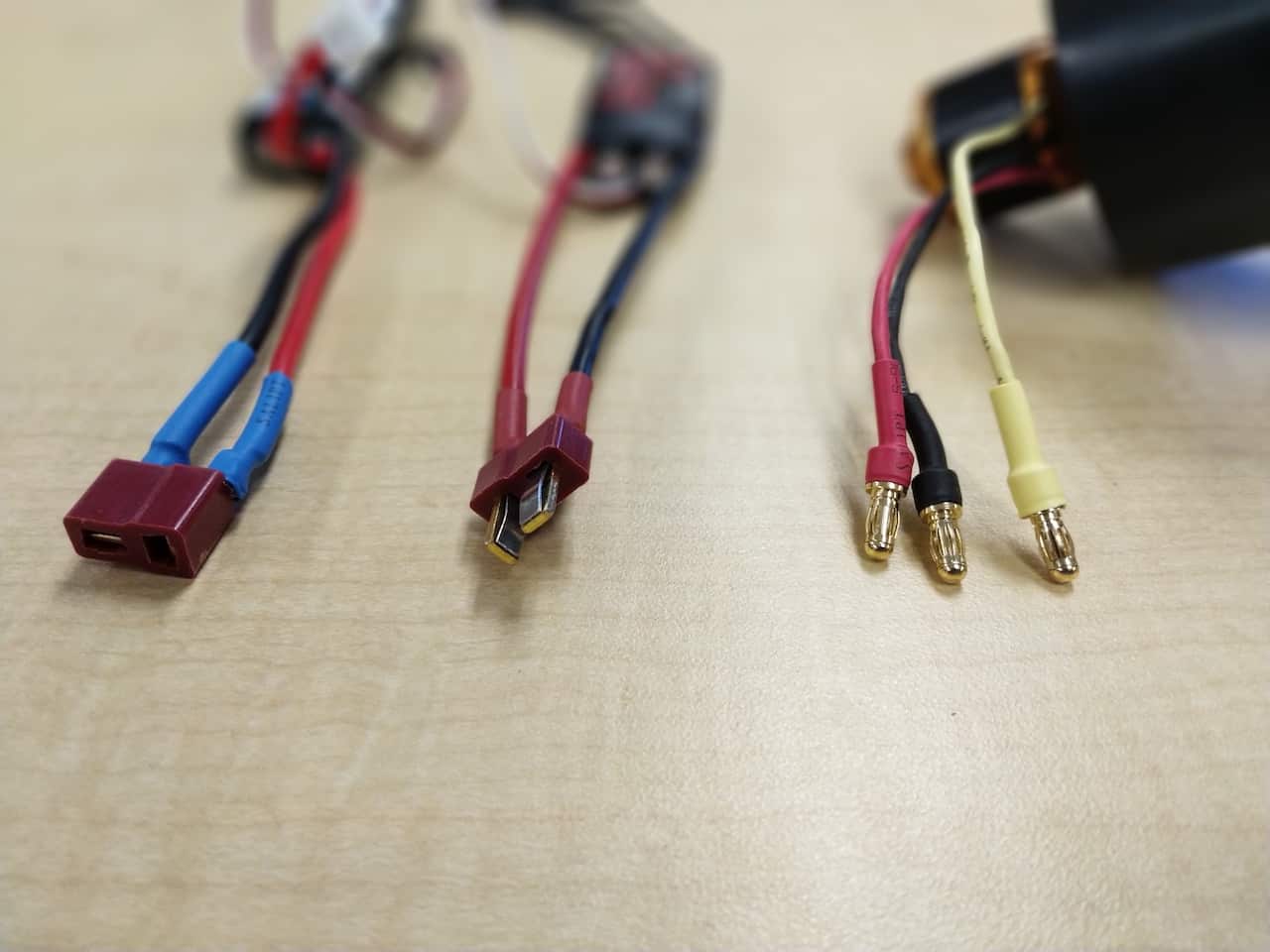
Connecting the electronics
First Milestone
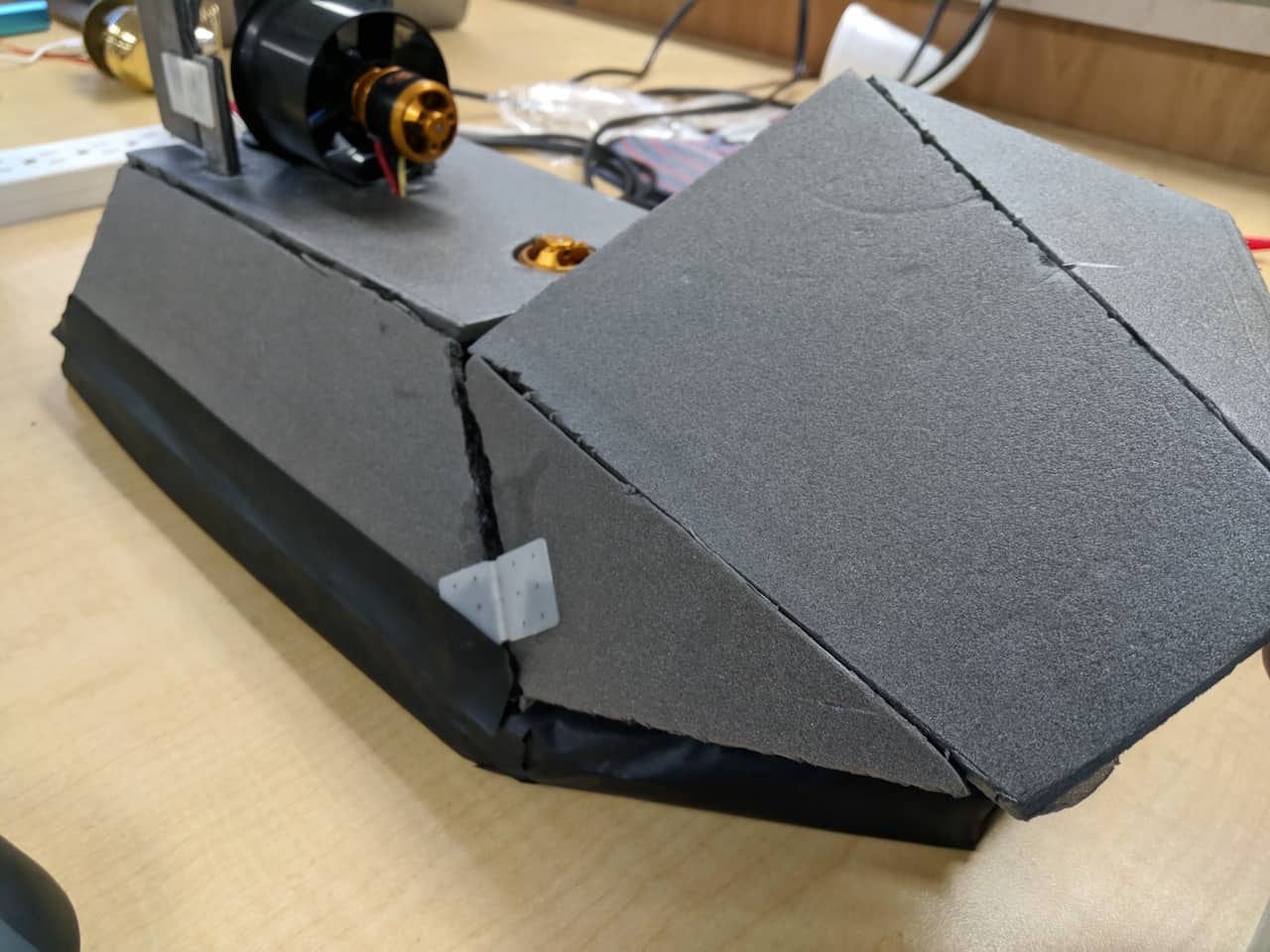
Building the body of the hovercraft
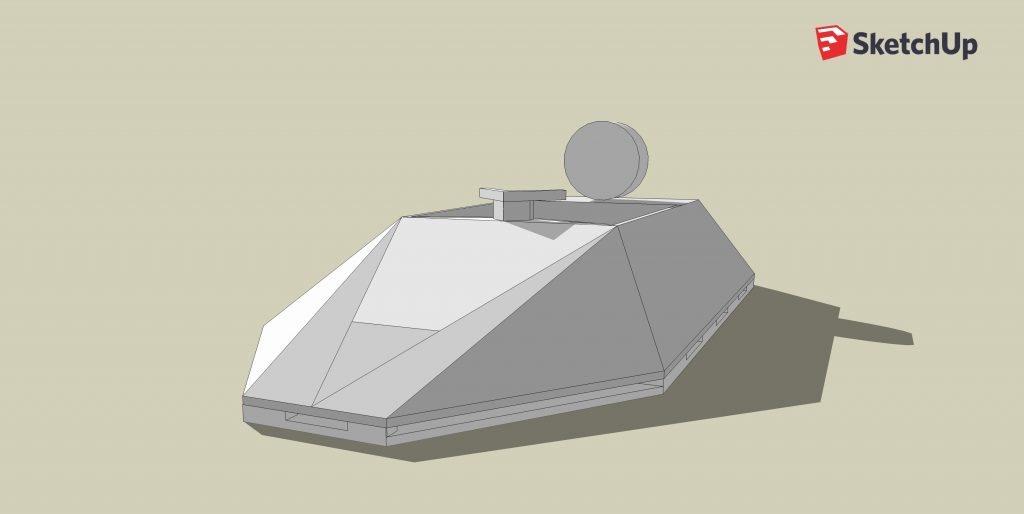
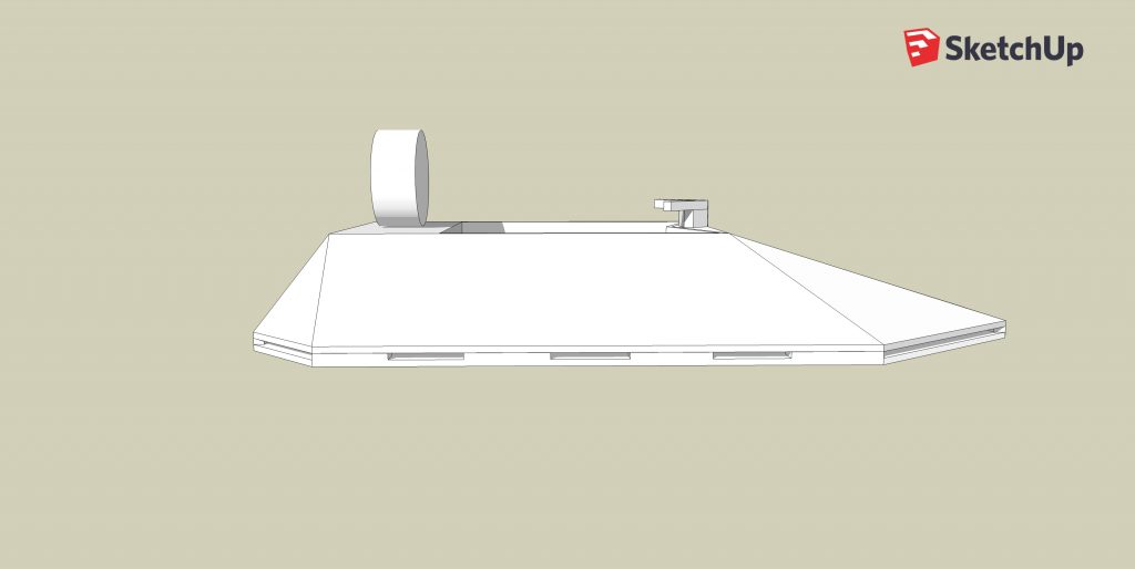
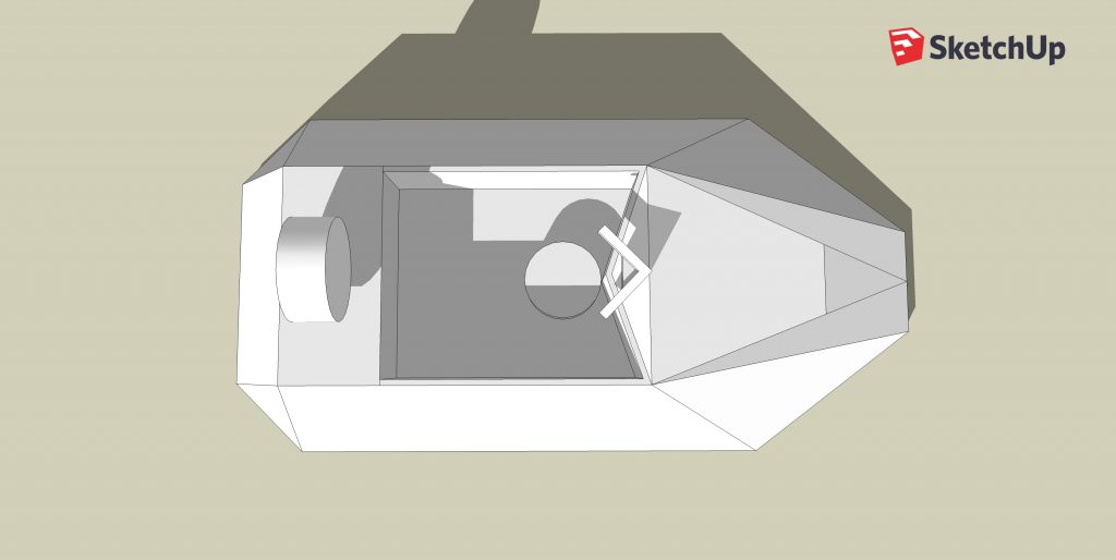
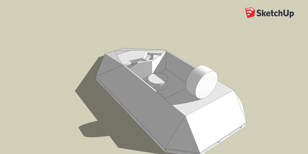
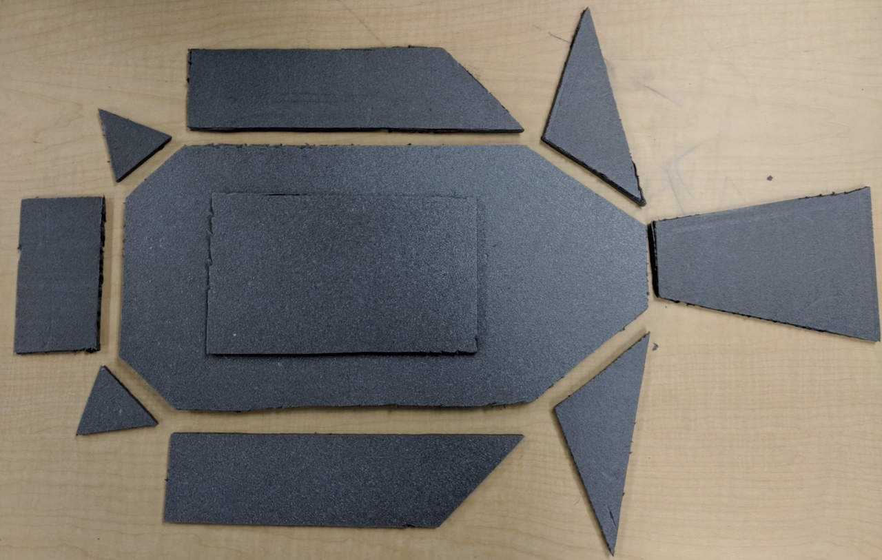
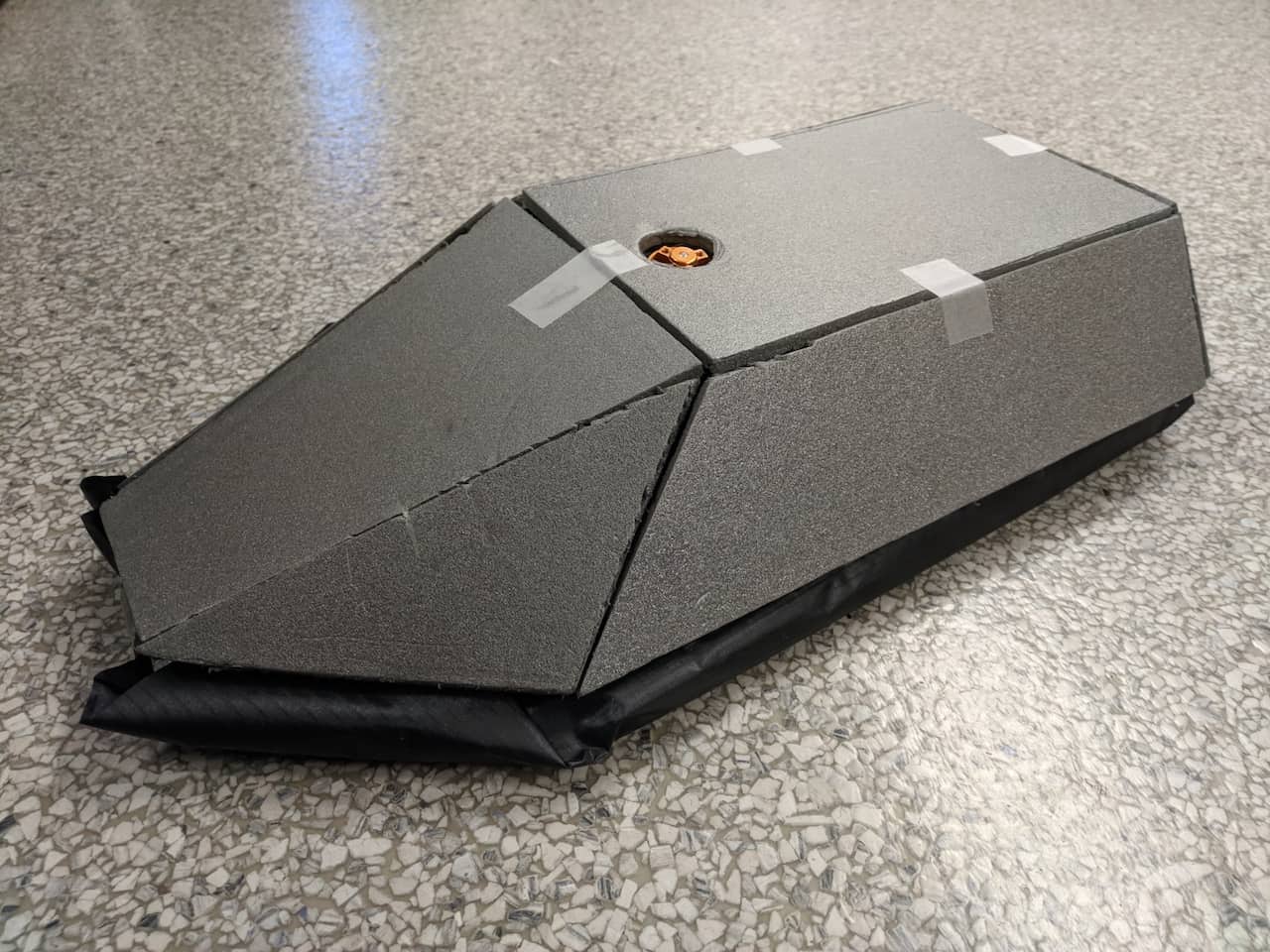
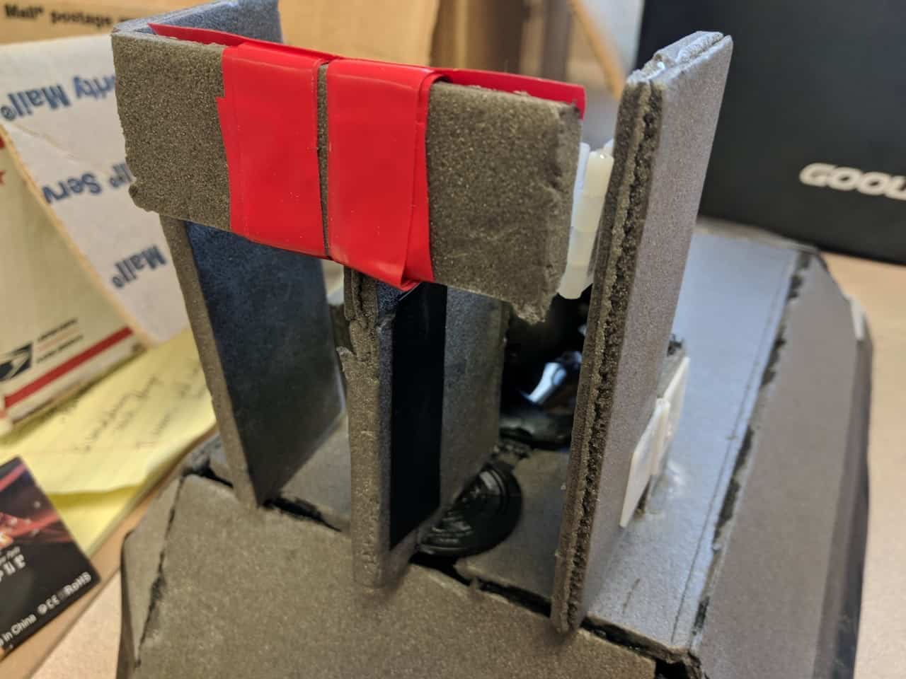
When gluing the body together, I decided not to glue the top cover of the body, because I was still unsure of the dimensions of the electronics and whether or not the skirt spread out airflow evenly. The skirt and the area covered by it are still easily accessible if I need to make changes. As for the rest of the body, I chose to use super glue because of its light weight and strength. I used tape to hold the pieces together while I applied glue and gave it time to set. The process went surprisingly smoothly, but I did get some glue on my fingers that I had to clean off with paint thinner.
Overall, this milestone took me longer than anticipated because tracing the parts onto depron proved to be difficult. Taping the pieces together also took longer than expected because some parts were not cut accurately and it was difficult to re-cut them.
The next milestone is getting all the electronics into the body of my RC hovercraft and working.
Starter Project
The useless machine