Welcome! My name is Ryan and currently I am a rising senior at Fairview High School. The starter project that I have chosen and built was the big time watch. My main project is to build a gesture controlled RC car with a robotic arm that I am basing off of an instructables. The RC car is controlled by flex sensors on a glove that sends the values to an Arduino on the car. Something interesting about me is that my parents own a restaurant that I go to after school everyday because we live far away from school, but the restaurant is closer. So my after school life consist of homework and working at the restaurant. Also, during sophomore year I built a water cooled computer from scratch. I picked out the parts and built the whole system by myself, which I think of as one of my greatest accomplishments.
——————————————————————————————————————————————————————————————————————
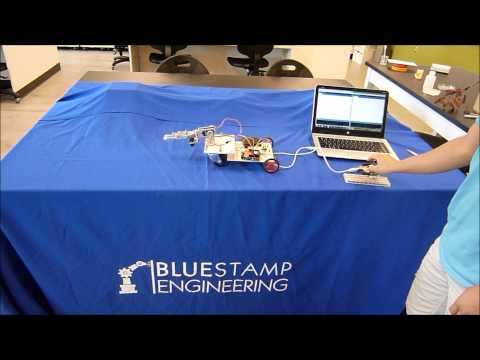
Milestone 3: Gesture controlled RC robot with a robotic arm (Main Project)
The gesture controlled RC robot with a robotic arm is a RC robot controlled through flex sensors attached on a glove that can swap between driving mode and hand mode. The base is made out of wood and has a central stack that houses an Arduino Uno, two battery packs, and a H-Bridge. The motors and claw/joint allow certain objects to be grabbed and then moved around.
For my third milestone, I have finalized the main components to my project, but there is still room to extend upon what has been done. For the base I added levels to house the battery packs and the Arduino Uno. Otherwise the base hasn’t changed much except for rerouting wires and finalizing the circuits by soldering them. The glove however had a lot more work to done than the base. The flex sensor and Arduino Uno needed mounting so I used rubber bands and hot glue. The wires also had to be soldered all together, but taking the process slow and planning ahead of time kept the issues to a minimal. The only problem I had with the glove was a broken flex sensor. I had the flex sensor replaced with a 2.2″ flex sensor so I had to swap spots with a longer flex sensor. For software I had all the functions in place so I just needed to change the code for the extra flex sensors. Otherwise the changes needed to for the coordinator was also the extra flex sensors, but also some fine tuning to mobility of the base’s components.
The robots functionality begins with the router Arduino on the glove which sends values to the coordinator Arduino on the base. The router Arduino converts the flex sensor values so that they are optimal for reading. The converted values are then sent to the coordinator Arduino which uses the values to run the motors to make the robot go forward, backwards, left, or right. Also, the values are used to control the angle of the joint and claw servos. For controls I use different finger motions to differentiate between functions. The pointer finger is used to go forward, the middle finger is used to go backwards, the ring finger is used to go right, and the thumb is used to go left. When the button the router Arduino is pressed the led lights up which indicates that it’s now in hand mode. The flex sensor values sent to the coordinator are now used to change the angles written to the claw/joint instead of controlling the motors.
Inspiration for main project: http://www.instructables.com/id/Handgesture-controlled-robot-with-robotic-arm/?ALLSTEPS
Build Plan: BuildPlanGesture-controlledRCcarwithrobotarm
Bill of Materials: Gesture-controlled RC car with robot arm- Bill of Materials
Base Mechanical Drawing (Google Sketchup): Base Blueprint
Base Mechanical Drawing (PDF): Base Mechanical Drawing
Router Code (final): router
Coordinator Code (final): coordinator
Base Wiring Schematic:

Glove Wiring Schematic:

Flex Sensor Wiring Schematic:

H-Bridge Wiring Schematic:

——————————————————————————————————————————————————————————————————————
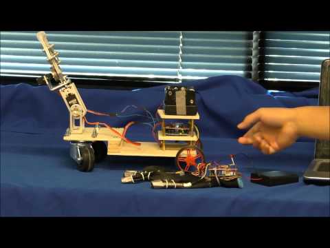
Milestone 2: Gesture controlled RC robot with a robotic arm (Main Project)
I have finally met my second milestone and for the most part the process was pretty smooth. Before I began the process of reaching my second milestone I began with being able to control the claw/joint with the flex sensors via the XBee connection. For my second milestone I created a wooden base and attached the claw/joint and motors to the base.
To begin my motors and wheels had arrived after finished up the first milestone so I first began the process with testing the motors to see their functionality. This meant I had to also learn how to wire the H-Bridge to control the motors. A side fact about the choice of using a H-Bridge is that it is a much cheaper solution than buying a shield for controlling the motors. In our case the functionality of the H-Bridge works for our purposes and learning the use the H-Bridge wasn’t all the too bad as the wiring wasn’t all too complex.
Next I worked on the base of the robot. Originally I wanted to make the base out of aluminum, but due to a downgrade in motor power the aluminum seemed too heavy. So I used wood instead which ended up being a lot sturdier of a solution than I expected. I first had to make a 3D sketch up of how the base would look and how I wanted the dimensions. Once I got the sketch up finished I got the pieces cut out and nailed them together through a column between two larger wooden rectangles that are staggered to compensate for the height difference between the trolley wheels and motor wheels. Overall the base turned out a lot better than I expected, but I ran into the problem of having too much weight in the front when I added the claw/joint. However, I expect everything to balance out once I add the levels and the other parts to the back.
Lastly, I added motor functionality to the code which was just a few digitalWrite() statements for the coordinator Arduino. I had to coordinator code set to always have the motors running just that if the flex sensor values are over a certain point the wheels will turn one way while the wheels will turn the opposite direction if the flex sensor is below that certain point. The code for the motors isn’t too complex and runs with the servos because I only have two flex sensors. For the final product I want to split the functionality so that the user has more options instead of using only two fingers to control everything.
Throughout the process I ran into issues with the XBee connection and had to reset the code by re-uploading the code to the Arduinos. The issue only occurred twice and hasn’t happened another time so I don’t think it’s a major issue that will occur with the final product. Lastly, I ran into some issues with powering the motors and servos together. The problem is similar to the issue before, where the joint servo wasn’t receiving enough power, but the issue was with my wiring because I was using the 5V from the Arduino again.
For my next milestone I want to finalize all the parts on the base and in the code. The process shouldn’t be too complicated as all the tedious work has been done and the process should be combining everything that I’ve done before.
——————————————————————————————————————————————————————————————————————
Milestone 1: Gesture controlled RC robot with a robotic arm (Main Project)
My main project is a gesture controlled RC robot with a robotic arm. The project is based off of an instructables made by mysqo and I am using it as a reference for troubleshooting issues, but otherwise I am trying to build the project by manipulating similar examples from the internet.
The electronics consist of Arduino Unos, XBee shields, Xbee S2s, flex sensors, servos, motors, and a H-Board. The Arduino Unos works as the brains of the system, but without the Xbee S2s the Unos wouldn’t be able to communicate with each other without wires. One Uno is in the car while the other is mounted on a glove with the flex sensors. The flex sensors are variable resistors that increase in resistance as the sensors are bent, so the voltage out decreases. The decrease in values from bending the flex sensors is utilized in the project to control the robot by the changing values. For example, the changing values can remapped and used to change the angle of a servo from the bending of a flex sensor. The final product sends the flex sensor values through the Xbee S2s to the other Uno that is coded to use the values to control the two motors and the two servos. With all the components we get a glove that can control an RC robot with a robotic arm.
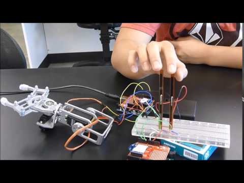
In this milestone, I have established a connection with the two Xbee S2s and have coded the two Unos so that I can bend the flex sensors to move the claw/joint connected to the other Uno. To establish the connection I set the Xbee S2 connected to the Uno with the flex sensors to the router AT function and the Xbee S2 connected to the Uno with the claw/joint to the coordinator AT function.
Although this milestone was not reached without any issues. I ran into a lot of issues trying to get the two Xbee S2s to communicate with each other and I believe that my issue was having the two functions mixed up. When I changed the two around a bit I could get the two to communicate. Another issue I ran into was trying to run the two servos and flex sensors off of 5V from one Arduino.
For my next milestone I want to finalize my wiring. To do this I want to add all the components wired and get them working with the flex sensors.
——————————————————————————————————————————————————————————————————————
Starter Project: Big Time Watch
Starter Project: https://www.sparkfun.com/products/11734
The Big Time Watch is a NATO style watch that displays the time when a button is pressed. The watch is composed of an ATMega328, one 32kHz crystal oscillator, one 4-Digit 7 segment display, one 10kOhm resistor, two .1uF capacitors, one button, one coin cell battery holder (powered by a coin cell battery), and enclosed in acrylic casing. The resistor and capacitors help keep the voltage from the coin cell battery constant for the ATMega328 and the crystal oscillator. The crystal oscillator vibrates around 32,000 times per second which is used by the ATMega328 to keep track of time. When the ATMega328 counts 32,000 vibrations from the crystal oscillator, the ATMega328 processes this as a second which is used to keep track of time. The ATMega328 came pre-programmed and that included the battery saving feature of only displaying the time when the button is pressed.