

Final Metal Detector
Hi! My name is Ruby and I am a rising junior at the Hewitt School. Before participating in BlueStamp, I had a some experience in engineering through the ACE mentor program, and working on my Science Olympiad projects, but Bluestamp has taught me so much more in such a small amount of time. When I worked on my starter project, the Sparkfun Gram Piano, the first thing I learned is how to solder and desolder. Within my starter project I also learned the basics of a circuit, (what a transistor, resistor, and capacitor do.) In my intensive project I learned how to use a breadboard, how to overcome challenge in a creative way, how to use an Arduino, and so much more. I have had such a great and educational experience at BlueStamp. My favorite parts were the independence that I was given and coming up with solutions to problems that continued to persist.
Second and Final Milestone
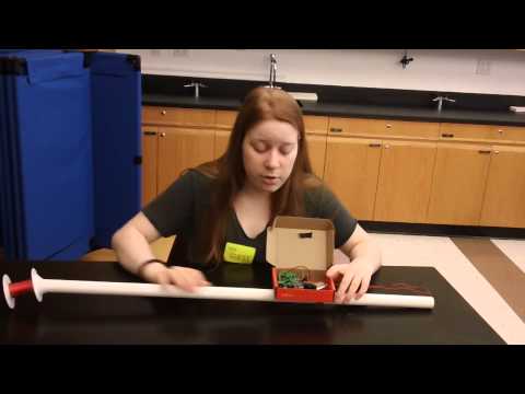
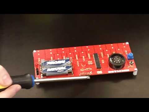
For my second and final milestone, I made a few adjustments. The first modification I made was transferring my circuit from a temporary surface, a breadboard, to a permanent surface, a solder-able breadboard. This gave me many problems. The first complication I faced was that I placed the push button in the wrong place. I connected the push button to both sides of the resistors, rather than only only side. Because of this, my whole circuit was shifted over a node. I had two ways to approach this situation, to either desolder the resistors, or desolder the push button. Then I realized if I desolder them, I would also have to desolder all the other components because they would still be positioned incorrectly. So, my next step was resoldering all of the components onto a different PCB board. Rather than having a PCB board that acted like a breadboard, for this PCB I would have to make the connections with solder. This was working out well, until I realized I soldered my transistor on incorrectly. Desoldering this transistor was difficult, because many other components were surrounding it, and because my soldering iron was touching them, it was melting the board and the other components. So, I went back to the solder-able circuit board. At this point, I had a lot of experience soldering this circuit on to PCBs, so resoldering this circuit went very smoothly for me, and it finally worked! I made two other adjustments. The first other adjustment I made was to the search coil. Instead of using hook up wire, I used magnet wire. Because of this, I had to adjust the sensitivity in the code to 125 rather than 1000. This brought down the sensitivity in the code, but ultimately increased the sensitivity because of the amount of wire I had. Lastly, instead of using a USB to plug into my Arduino, I used a 9 volt battery and connected it to my Arduino. This makes my metal detector portable. To complete the project, I used PVC piping and a box. I strung the magnetic wire through the PVC piping and put my circuit in a box. Thats how I made my metal detector!
Documentation
Schematic:

Code (with modification): Sensitivity changed from 1,000 to 300:
https://dl.dropboxusercontent.com/u/2248531/blog/metal_detector/metal_detector.ino
Bill of Materials:
https://docs.google.com/spreadsheets/d/1UZNdyJNxXZ2zgjeGmnhAEoKputGQl33qIOgJ2zlzwlQ/edit#gid=0
Picture of circuit, Arduino, and power source:

First Milestone: Arduino Based Custom Metal Detector
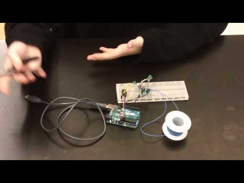
For my intensive project I am working on an Arduino based custom metal detector. I chose this project because when I was reading through the project book, this project seemed interesting, and it would be fun to have after the project was complete. After breadboarding my circuit multiple times, I finally took a different approach, and it worked! Instead of wiring the breadboard around the Arduino or randomly wiring the breadboard, I worked around the transistor. While I was building my circuit, the transistor was my reference point. This approach used fewer wires and was an easier circuit to understand. There are four main parts that make the metal detector work; the transistor, the search coil, the Arduino, and the push button. The transistor I used was a bipolar junction transistor model number bc547. This transistor has three terminals; a collector, a base, and an emitter. Transistors are responsible for two things, controlling the current that flows through the circuit and switching the current on and off. The current that flows throughout the transistor goes through the collector and leaves through the emitter. The base is the terminal that turns the current on and off. A bipolar junction transistor is controlled by the amount of current that flows through the base terminal. The Arduino I used served two purposes; to hold the code that makes the metal detector work and to provide a power source of the machine. When you first turn the metal detector on, you need to press the push button to null the machine. Part of my circuit is fed to pin 5 of the Arduino. The Arduino code that I used measures the frequency of pin 5 very well so when the null button is pressed, the frequency of pin 5 is stored in the Arduino, which stops the buzzer from buzzing until metal is near the search coil. The search coil is a very important part of the metal detector because it is able to detect a change in the magnetic field. Magnetic field changes when metal is introduced to the search coil. This change creates a current, which is put into the coil. This change in current is detected by the transistor, which then tells the buzzer to beep quicker.
Starter Project: Sparkfun Gram Piano
For my starter project, I made the pre-programmed Sparkfun Gram Piano. I used capacitors, resistors, a microcontroller, and other necessary parts. When I first built the Gram Piano, it did not work. At first, I thought there was a problem with the microcontroller because other parts of the device were working. The LED lights were lighting up, and the speaker was working. So, I thought maybe the microcontroller was wiped of the code that programmed this device. So, I figured out the code and tried to upload it to the piano. But, the uploading of the code failed multiple times. So, this further lead to my hypothesis that something was wrong with the microcontroller. I was stuck. So, I emailed another instructor who had experience with the piano and he said the problem was most likely not with microcontroller. He said something might have blown, or a component was inserted incorrectly. It is very possible that something had blown, but I believe that everything was inserted correctly. If a piece was inserted incorrectly, I think that the speakers and the LED lights would not have worked. So, I was given two options, to either restart or to try to desolder the microcontroller. I decided to rebuild the Gram Piano just in case there was another problem of which I was unaware. So, after I built my second Gram Piano, it worked! The LED lights were lighting up, the speaker was able to play the preprogramed song and the piano keys were working!
The Gram uses many different pieces. It uses two LED lights, the light on the far right indicates that the piano is on, and the LED in the center of the board tells if the piano is ready to be played. There are two batteries that provide power throughout the board. The capacitors are used to store the electricity that is released from the battery. The resistors are used to help balance the amount of electricity flowing through the device, by reducing the amount of electricity that is released by the batteries. Then you have the speaker, which releases the sound, the play tune button that when pressed plays a pre-programmed song, and the octave select, which when turned changes the octave of the song and keys. The right angle header is a piece that is used if you want to recode the device. Then, there is the power switch, which turns the device on and off. The microcontroller is used to hold the code that is programmed on the piano. The battery holders help deliver the energy that is released from the batteries to the rest of the device. Lastly, the way the keys work is through the capacitive touch keyboard. When you touch the keyboard, the measure of capacitance changes that sends a signal to the board creating the sound.