3-D Printed Robotic Hand
My project is the glove controlled 3-D printed hand. It is controlled by flex sensors on the glove. It uses Arduino as well.
Engineer
Rohit T.
Area of Interest
Robotic prosthetics/augmentation

School
Harker High School
Grade
Incoming Freshman
Reflection
My time at Bluestamp Engineering has taught me more about both electrical and mechanical engineering. I’ve also learned how to code, something that I was very unsure about before this camp. This is mostly due to the project I chose. I was originally planning to choose a completely mechanical project, but the risk I took with this project ended up helping me in the long run. I still had many problems with this project though. One of the most challenging problems I had was when I had to spend an entire week trying to learn and understand the Arduino based code. As I said before, I was not that good at coding, especially with Arduino. However, I still managed to overcome this problem with the help of the staff members, and was able to make my project work. Despite all the problems I had at this camp, it was still a very enriching and teaching experience, and I am grateful that could participate in this program.
Final Milestone
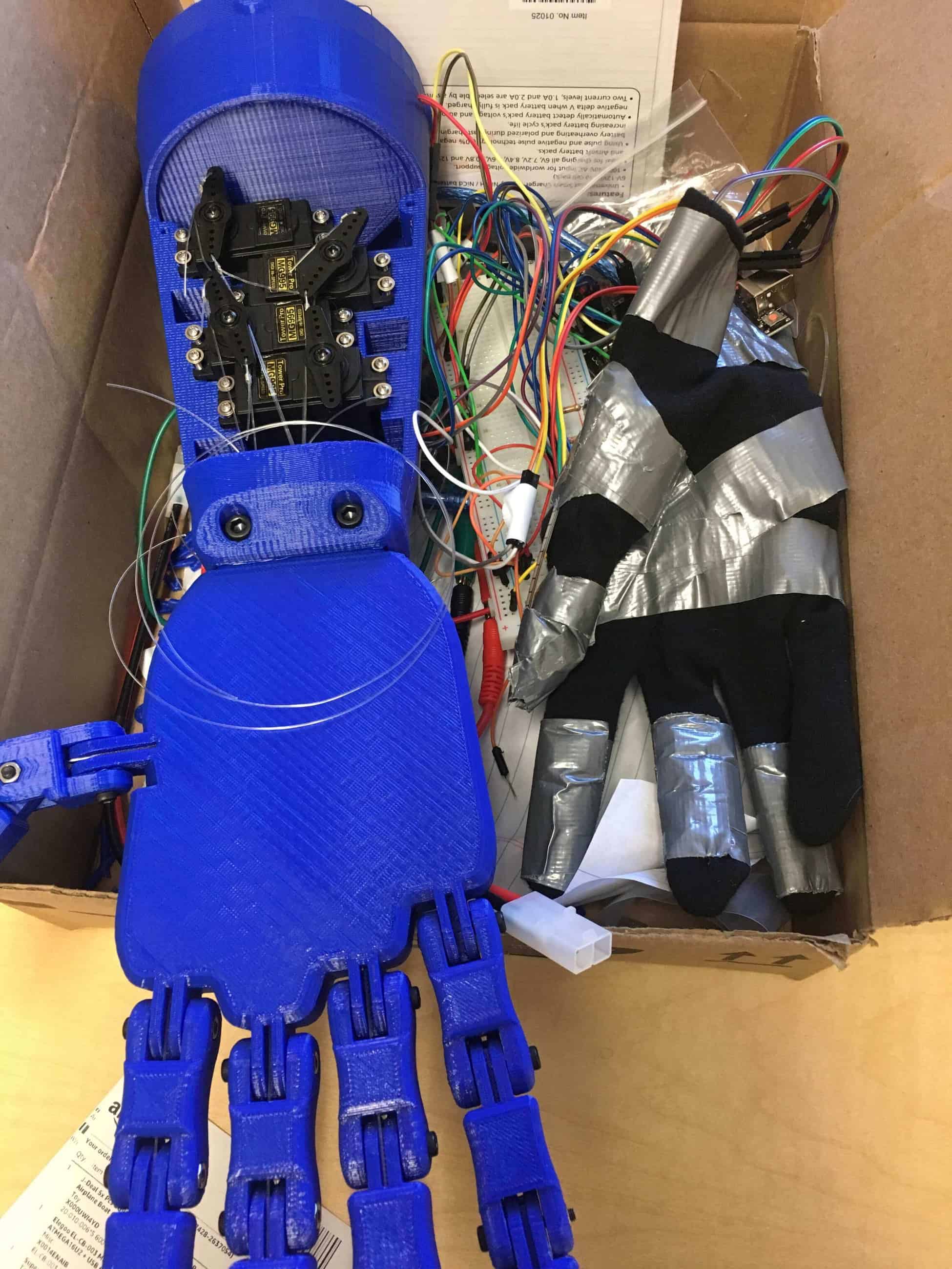
For my final milestone, I inserted all my servos inside the arm, and attach fishing line to them from the fingers so the fingers could move independently. This was the hardest milestone I had done until this point since I had to learn how to do a lot of different things. For example, I needed to use crimp tubes rather than knots to attach the fingers to the servos. I ended up breaking a few crimp tubes by accident when I damaged them too much. I also had a lot of trouble with the fishing line itself. The first time I tried it, I made the fishing line too short and had to retry stringing it. Because of this, I ended up wasting an entire session trying to redo what I did the day before. To add on, the servo for the ring finger was loose, and would not pull the ring finger properly because of this. I decided to tighten the fishing line so that it would be able to move the finger better, but I wasted some time trying to tension the line. Another problem was that I only had 4 servos, but the hand came with 5 fingers, so I had to decide what configuration I wanted. I chose to use my ring, middle, pointer, and thumb. For a possible modification, I might make it so I can control my pinkie as well.
Third Milestone
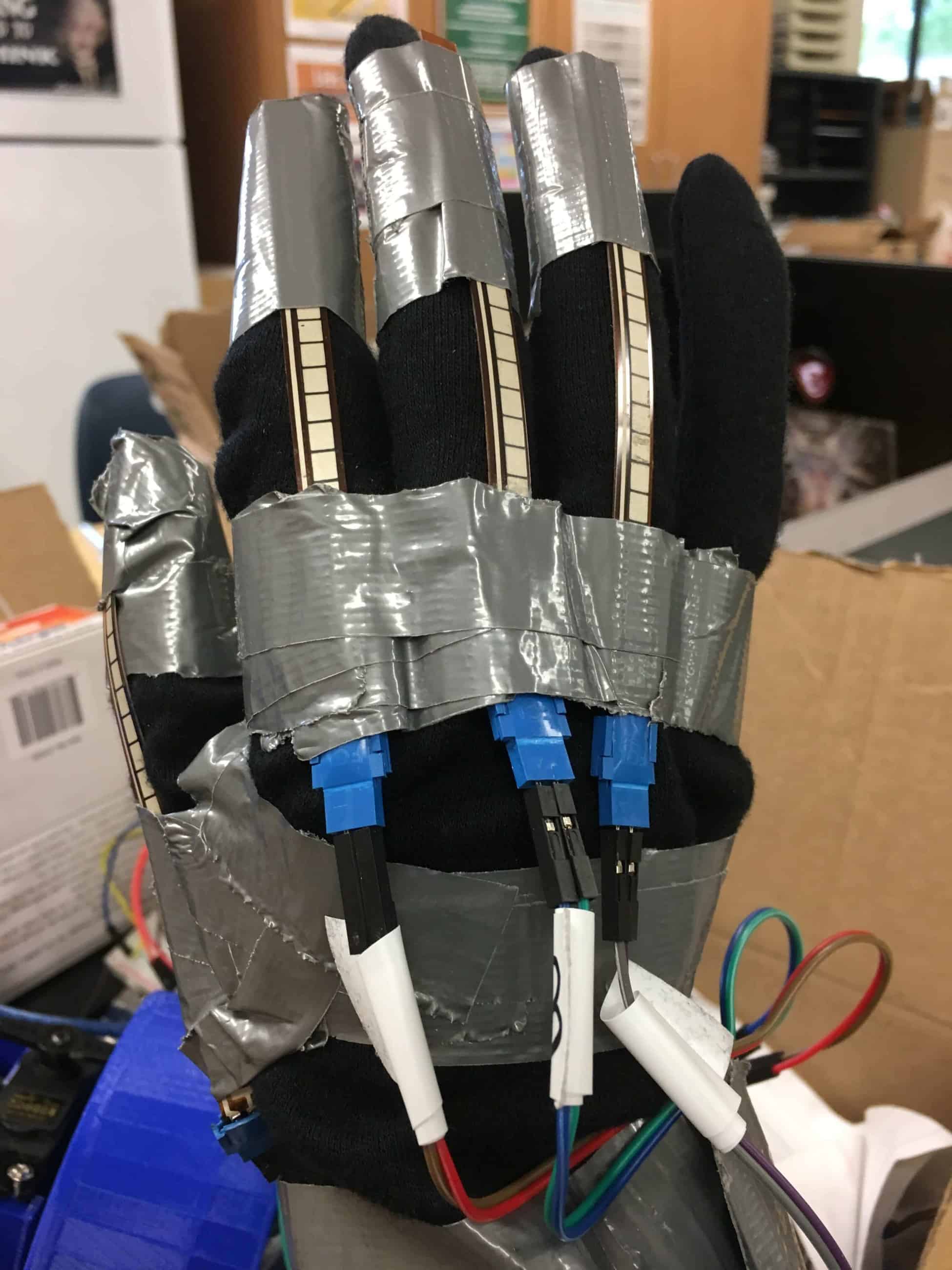
For my third milestone, I built my glove and hand. To attach the flex sensors to the glove, I used duct tape. The directions said to sew the sensors to the glove, but I thought that would be to easy to mess up since I am not that good at sewing. To add on, since I was already behind because of my issues with my breadboard, so I wanted to use the fastest method. A problem I had was that the duct tape made the flex sensor bend unnaturally when I wrapped it around the entire sensor. Because of this, I had to figure out a way to fasten the sensors without damaging them. I eventually found a good configuration for the duct tape though. I also was originally planning to solder everything to a PCB, but since the arm doesn’t move around there was no point, so I kept using a breadboard. Finally, I added a simple fastener for my wrist, since the glove was too big. The hand itself was actually easy to construct since all I had to do was screw the fingers together. However, it did take a long time make. For my next and final milestone, I’ll be putting all the servos in the arm and connecting them to the fingers with fishing line.
Second Milestone
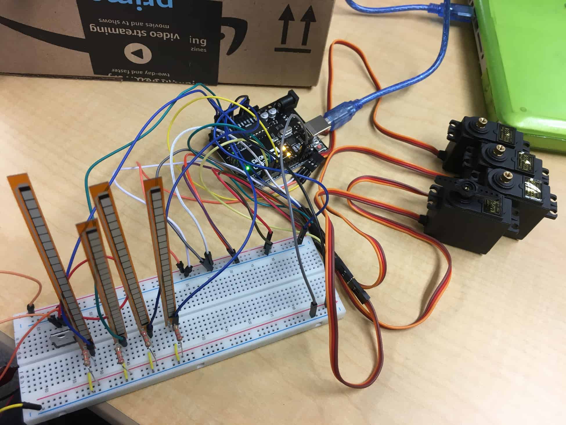
For my second milestone, I made a circuit with 4 flex sensors and servo motors. This milestone was easier than the first because I just had to do the same thing but 3 more times. To make things simpler, I used only 1 breadboard instead of 2. In my code, I just made 3 copies of what was already there and changed some of the values and pin numbers. I also decided to use the Arduino to power my flex sensors, but an external power source for my servos. Some challenges I had were that I had to remap some values just like I did with my first milestone. To add on, since my external battery gives out 7.2 volts, I needed to learn how to properly place and use a voltage regulator, which regulates the output of voltage from a power source. This proved to be hard because I had never used one before, not even in my starter project. It was also a challenge to keep all my components neat and away from each other so their wires would not get tangled with each other. I thought about color coding my wires, but I ultimately decided not to since it would take to much time. All in all, this milestone was a lot simpler than my previous one. My next milestone will be building the hand and putting all of the components into it.
First Milestone
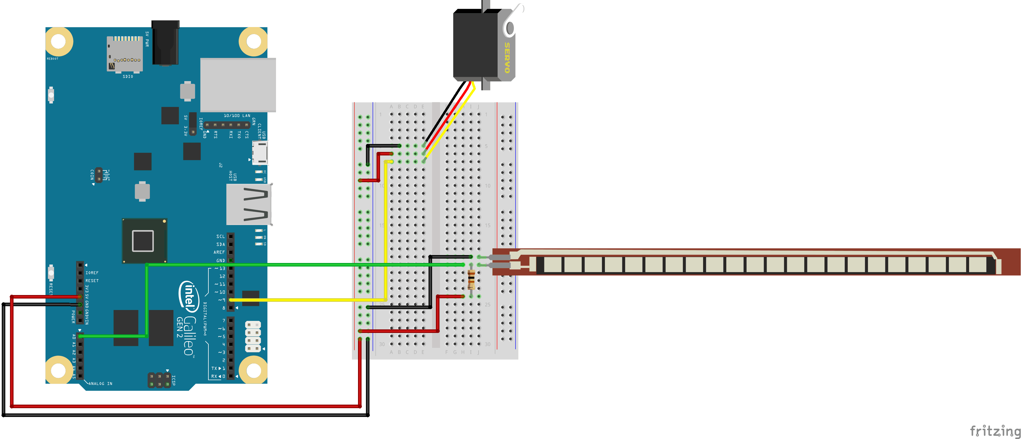
My main project is the 3D printed robotic hand. For my first milestone, I began work on one of the servos and flex sensors. The servo moves whenever the flex sensor is bent. The way it works is that the flex sensor is a resistor, so when it is bent it changes the resistance of the circuit. Since a change in resistance causes a change of voltage, the Arduino can measure the change in voltage and start the spinning the servos. I had a lot of challenges with this milestone. One of the problems I had was that the breadboard I had was actually broken. This was difficult to figure out since the breadboard was the one component I thought was guaranteed to work. To add on, I also had to use Arduino to program everything but I didn’t know how to code with it. Because of this, I had to teach myself how to program with Arduino. I also used the serial monitor to see what the values of my flex sensor were and remapped them to values the servo could use. For my next milestone, I will try the same thing but with four flex sensors and servos instead of just one.
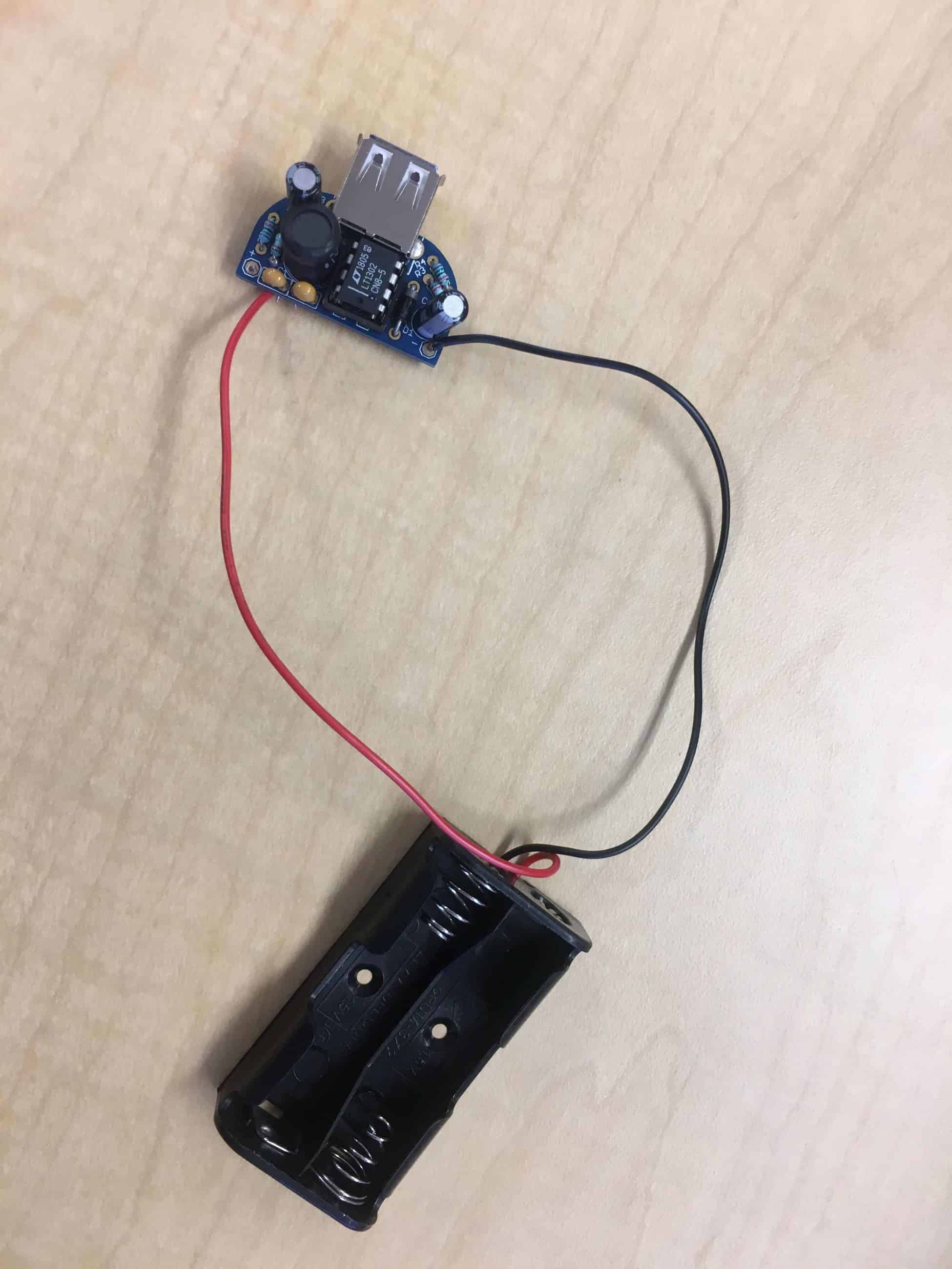
Starter Project