
Welcome to my project portfolio! My name is Rohan S. and I am a rising Freshman at the Harker School. My main project is to construct a Hand-gesture Controlled Robot with Robotic Arm. I have based most of my work from this previous project. It uses a wireless connection to send signals in order to perform different tasks controlled by the flexes of different fingers by the user. For my starter project, I built the Big-time Watch Kit which taught me a lot about basic concepts of engineering and specific parts of circuits.
I have been interested in building projects for as long as I can remember. From this project, I have decided that I am really interested in software engineering because of how much fun it was to program the flex sensor readings to be read by the micro controller(Arduino) and then wirelessly sent over to the other micro controller(Arduino) to perform a task to either move the robot or pick up an object using the robotic arm. Even though it was very frustrating to find extremely trivial problems in my code which were sometimes the root of a major issue in my project, it was worth it because of how much I learned about C++ programming and coding logic in general. I also learned some valuable troubleshooting tricks including isolating an issue so it becomes easier to find the right solution. Overall, the issues and setbacks all helped me grow my passion for engineering and also made it clear to me what kinds of activities I would like to pursue as I enter my first year of High School.
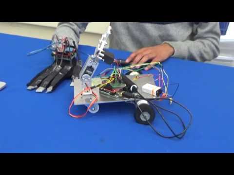
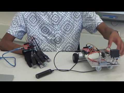
For my final milestone, I made the glove work wirelessly with the robotic arm and the motors. The wireless communication logic has remained the same so the really the only new part is the motor driver or H-bridge. The purpose of an H-bridge is to be able to control a motor through my micro controller and allow me to decide what direction I want each motor to be spinning in by setting the state of the two motor pins to either HIGH or LOW. This process took me a while because I had a lot of trouble with finding an H-bridge that could handle the current being used by the motors. In the end I had to change the motors I was using and also the motor driver.
Final Schematic:

My third milestone was to wirelessly move my robotic arm. Like before, the XBee send a single character which is received by the other XBee and then converted into a signal. Something new I added was that now I can switch between two modes, “Arm Mode” and “Motor Mode”, which determines what part of the robot to control at any given moment. Although I cannot make my motor work as of now because I have not received my H-bridge to control the motors. One issue I had earlier was that my servos stopped working as soon as I plugged in my 12V power supply into the arduino. Later, I realized that it was too much voltage and that a 5V Anker supply would work better. Tomorrow, I will attach my motors to the driver and set up all the hardware because I have already written code for both the arm and the motors. Also, I will need to add a gesture to toggle between modes.
My second milestone was to wirelessly turn on LEDs by using XBees. The arduino reads the flex sensors that are plugged into the pins specified in the code, when the analog reading goes below 60, the arduino is programmed to send a single character through the XBee to the other XBee which is connected to the arduino that controls the LEDs. When the second arduino receives the char, it runs a switch statement to determine which LED to turn on. The XBee’s serial connection uses a technique called bit banging which uses software rather than hardware to control the states of the pins on the arduino. I learned a lot from this milestone including writing and debugging arduino code with Xbees, PWM, configuring XBees, and the wireless connection. The main problems I had while working toward this milestone, were that my flex sensors were not being read and I had never programmed XBees. To fix my flex sensors, I had to resolder the sensors to the wires a couple times. This was tough because often times the sensor got burnt in the process. For my XBee program, I did some research online and then wrote my own program by sending text to one Xbee which was then converted into a signal to turn on an LED. Looking forward, I am going to start working on the chassis of my robot and putting all of the separate parts together.

My main project is a hand gesture-controlled robot with a robot arm and my first milestone was to connect the flex sensor circuit to a breadboard to test that the arduino could track the values and then interpret them by outputting a light in the LED when a specific combination is pressed by the user. I used analog pins because I needed to intake a variety of inputs instead of a simple ON or OFF. When the flex sensor is bent, it increases the amount of resistance which decreases the voltage received by the arduino. For my specific sensors, the analog reading was around 680 or above when unbent and around 520 or below when bent. I learned about variable resistors, specifically flex sensors, arduino code, how a breadboard works. and the connection between an input device, an arduino, and an output device. The fact that the flex sensor is a type of variable resistor means that when the user bends the sensor, it changes the amount of resistance in the circuit which the arduino can pick up. When the arduino receives this signal, it is programmed to either keep the LED off or activate it. It makes this decision based on the value it receives; if the analog value is less than 520, it turns on other wise it stays off.
As I worked on this part of my project, I encountered an issue where the arduino was picking up the signal from the sensors, but did not switch on the LED. In order to decide whether the problem was if the arduino was able to make a decision based on the value it receives or if there was a problem with our circuit, I inserted a print statement within the if statement that only printed if the arduino reached this part of the code. When the console printed out the numbers properly when activated by the sensors, I concluded that my problem lay in the breadboard. At first I thought the issue was that the 5V was not enough to power four flex sensors along with four LEDs. In the end, I decided that the real problem was that in between the breadboard there is a gap, so I simply needed one wire connecting the two hemispheres of the board. Another problem I had to keep watching for was that sometimes our wires were not aligned and this caused the circuit to not be complete. Looking forward, I am going to start working on the Xbee which will be used to help the arduino on the glove communicate with the arduino on the robot and vice versa while eliminating a wired connection between the two.
Schematic for Flex Sensors:


My Big-time watch taught me how to solder components together and I also learned about the parts of a basic circuit. When I press the button on the side of the watch it completes the circuit on the interior which causes the display to show the time and if one were to hold the button down, the time would start blinking to signal that the user can now change the time by continuing to hold down the button. I learned what resistors, capacitors, and crystal oscillators do and what they are used for. A resistor is used to control the current running through the circuit and also prevents short circuits from occurring. Capacitors hold extra electric current in case the battery runs out so it can take control of the circuit in an emergency. Crystal oscillators oscillate or vibrate at a precise frequency and because this frequency is so precise, this device can be used to keep track of time, thus a main component in my project. As I was working I also encountered quite a few challenges. One of my biggest challenges was after soldering all the parts to the board, I could not attach the casing of the watch to the actual board. When I tried to screw it together, the parts kept on slipping off of the screw. To solve for this problem, I decided that instead of trying to stack the parts and then try to insert the screws, I would put the parts directly onto the screws so I could use gravity to my advantage.