
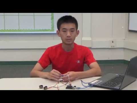
Welcome to my project page! My name is Richard, and I am a rising senior at Gunn High. I chose to build a 3 jointed robotic arm, which was loosely based off of Sasha’s, a previous student’s project. Here is his project link: http://www.bluestampengineering.com/portfolio-view/sasha/. This project was a great introduction to robotic coding, circuitry, and mechanical work. My starter project was the Mintyboost, from Sparkfun. This is the link: https://www.sparkfun.com/products/10094. This mini project was great for an introduction to soldering and circuitry building. Both were crucial to the build of my robotic arm.


Joystick controlled code
https://docs.google.com/document/d/1COl9j3NSws7ET_A5WIpdHpIG9Y5UYT5nwshVtbuO6pg/edit?usp=sharing
Keystroke code
Arduino code:
https://docs.google.com/document/d/1WdbaGo5QOVNGFmQxKKdfFTevVzP1nvMjYmaippxyzLQ/edit?usp=sharing
Processing code:
https://docs.google.com/document/d/1pvSj4Rxrf-cDZC8QtON0THL1nsHKp4J6cltFO_ove4M/edit?usp=sharing
Schematic

I used a program called Fritzing to make my schematic.
Reflection
I have learned more about engineering in these 6 weeks than I have my entire life. When I came to the program, I had no coding experience at all. Now, I have written 2 different codes: one for joystick uses and one for keystrokes. This is just one example of how far I have come. Besides learning coding, I’ve learned a plethora of useful engineering skills. I know how to solder, how to draw schematics, use Autocad, use power tools, dimension parts, etc. I encountered countless problems every single day, and the program taught me how to solve each and every one of them. There were obstacles I never dreamed I would ever encounter, and learning how to solve them was both frustrating and exciting. A great example is my power supply problem that I encountered near the end of my Bluestamp experience. I never thought that 6v differed that greatly from 6.5v or 7v, but I soon learned that my arm could not operate at 6.5 or 7 because they overloaded my circuits with power. I realized how important it is to use a multimeter to test power and circuits; without it I would have fried my circuits many times by now. However, this program has taught me more than just engineering. I learned how to set goals everyday and the importance of accomplishing these goals, no matter how small. By steadily achieving my small goals, I completed my project early, and had time to add modifications such as keystroke controlling. This was an experience I will write about for college, one I will endorse to anyone for a great introduction to my engineering career.
Completed Build
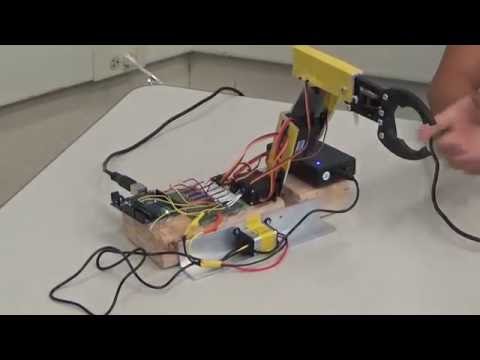
In the final stretch of my project, I implemented a Processing code, which allows me to send keystrokes to the arduino code, thus allowing me to control my servos with keys. I can do this because I mapped certain keys to certain turns. The code worked as expected; it made the whole arm smoother in motion, as well as simplifying my code. I solved the big power supply problem by installing a 12v power supply and a 6v regulator. Now, the arm is provided constant 6v. I also attached the arduino, PCB, power supply, and regulator to the base so the whole circuitry is portable. Finally, I gave the arm a cool look by using electrical tape to cover up scratches on the aluminum. I am very proud of how my project turned out.
Milestone #3
My milestone 3 was mainly finishing touches. Since milestone 2, I have added a wooden base with angle aluminum supports, soldered circuits onto a PCB board, and worked on a power supply problem. My biggest obstacle in this milestone was figuring out an appropriate power supply to attach, and then attaching one. The 5v battery did not supply enough power, so I opted for a 6v one. However, when it arrived, it charged up to 7v, which is too much power for my circuits to handle. My servos would ignore my commands and twitch uncontrollably. Because of time constraints, I used the Bluestamp power generator to film my milestone 3 video, which I will replace for a portable one as soon as possible. A problem I had in filming my video
Mechanical drawings
Along the way, I created dimensioned mechanical drawings of several parts I needed to cut out.
One section of arm: Wood base:


isometric isometric


top view top view


left view left view
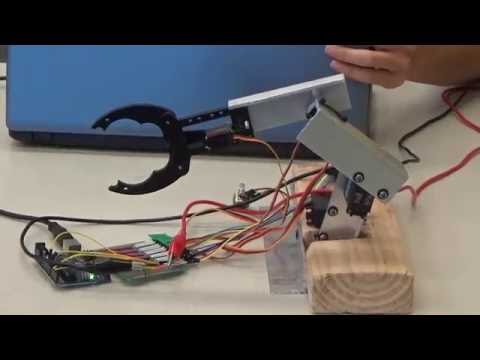
Milestone #2
My second milestone took a lot more time and effort, as I had to not only get more servos to work independently from each other, but also to build a real frame and working prototype. However, I found that as my coding and circuit experience grew, it wasn’t as painful to complete this milestone. When I started the milestone, I had the goal to control the servos independently with 4 different potentiometers, one for each joint. I soon found this to be impractical, so I switched to using a joystick. The joystick had 2 axis, and a button that activates when I pressed it down. While hooking up 2 servos to 2 axis was easy enough, the coding for the gripper to activated from the button was very challenging. The gripper couldn’t be coded the same for the other servos because it needed to open and close on a button, which has only 2 settings: on and off. This experience really taught me to be patient, as coding for the gripper took me a good week to complete. My next obstacle was building the arm parts. I used a hacksaw to cut out 3 pieces of angle aluminum to form my arms. A challenge I faced here was attaching the servos to the metal pieces. I quickly found that tape, glue, and epoxy were bad at attaching plastic to metal. I had to embrace the inner mechanical engineer. By drilling holes into the metal, I bolted in the servos with a combination of zip ties, nuts, and bolts. The product was a strong, stable connection between the servos and metal arms. However, my greatest challenge, one I wasn’t aware of until now, arose. My servos did not produce enough power to carry the weight of the arms. I tried to use 2 servos on the base, but the power produced from the 2 mini servos still was not enough. I spend 3 days exploring options, until I finally conceded and bought bigger, stronger servos. This experience was valuable in teaching me that sometimes the fastest way to move forward is to give up on a hopeless method. Finally, I emerged from weeks of struggle. My milestone #2 was a success, and I am proud of it.
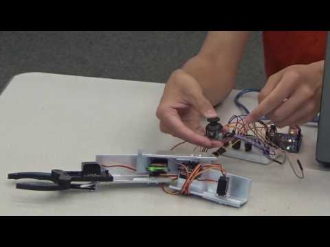
Milestone #1
I started out my intensive project with little experience in any of the main areas needed to produce a functional robotic arm. My starter project introduced me to circuit boards and soldering, but my main project involved a lot more than that. The first couple days were frustrating, as I had no idea how to start my project. Should I start by learning coding? Maybe programming the arduino? How about just building the arm? By searching similar projects online, I decided it was best to learn how to program the arduino first. I researched the components on the arduino and what it could accomplish, as well as how to attach and program a servo (joint). Having had no experience at all in this field, I struggled to understand why some aspect, such as the code, worked. However, by patiently and arduously working, I accomplished my first milestone. I had connected two servos to the same arduino/breadboard circuit, and both operated by the same potentiometer. I am proud that I did not copy someone else’s code or build, and although some lines of code are derivative from other projects online, most of the code and circuit board connections are mine. The problem with using a potentiometer is I cannot control the 2 servos differently; both will turn when I turn the potentiometer. To further my project, I will need to implement a 2 axis joystick and rewrite my code to accommodate for a second axis that essentially acts as a second potentiometer. I will also need to have the gripper function properly.
I have learned quite a lot in these couple of days working on my starter project. First, I’ve become familiar with a couple of basic engineering terms, such as soldering, desoldering, capacitors, resistors, diodes, power supply, and Ohm’s Law. I understand what these do, for example resistors are used to reduce current flow and capacitors store energy. However, I have encountered many obstacles along the way. One of my biggest problems is forming solder bridges, where two conductors touch ends. I spent an hour trying to desolder my solder bridges, which took not only time but also pain and sweat. From this, I learned that mistakes are inevitable sometimes, and learning how to fix that mistake is a valuable experience. A consequence from desoldering is the schottky diode sticks up because I had soldered it in backwards, and since it is nonpolar so current only flows in one direction, I had to desolder it. Desoldering was my biggest struggle, but I feel good that I learned to overcome it.