Project
Thermal Imaging Camera
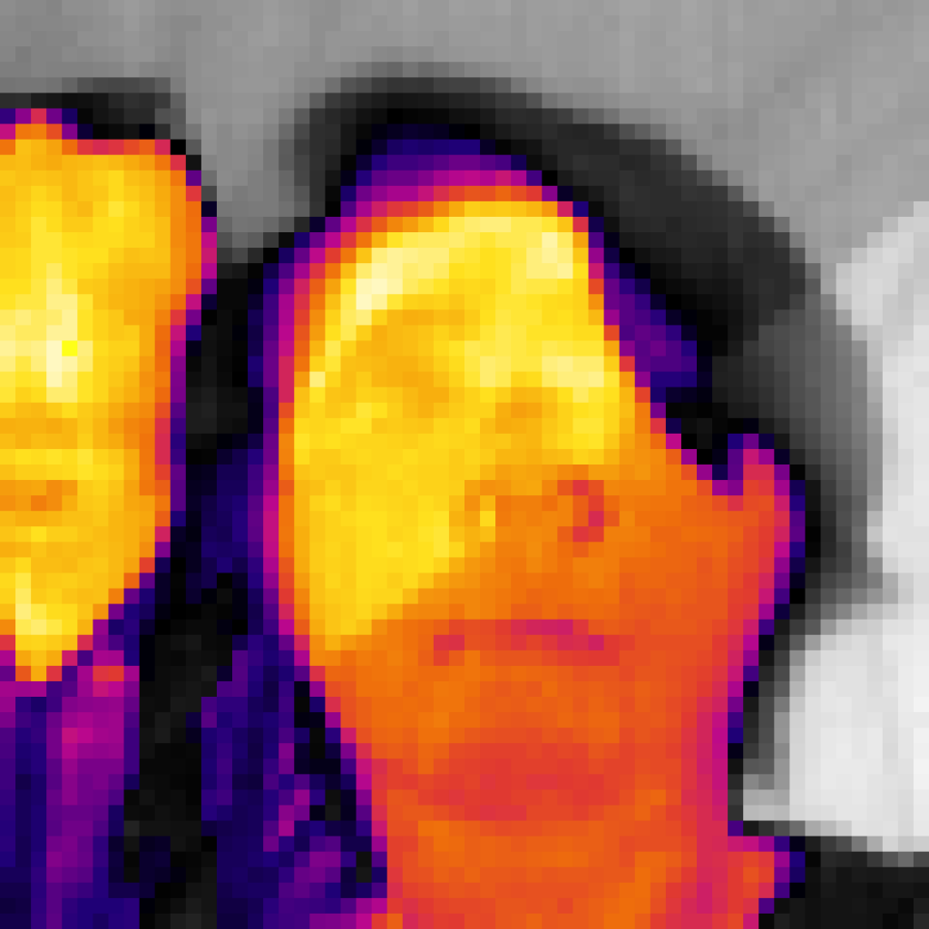
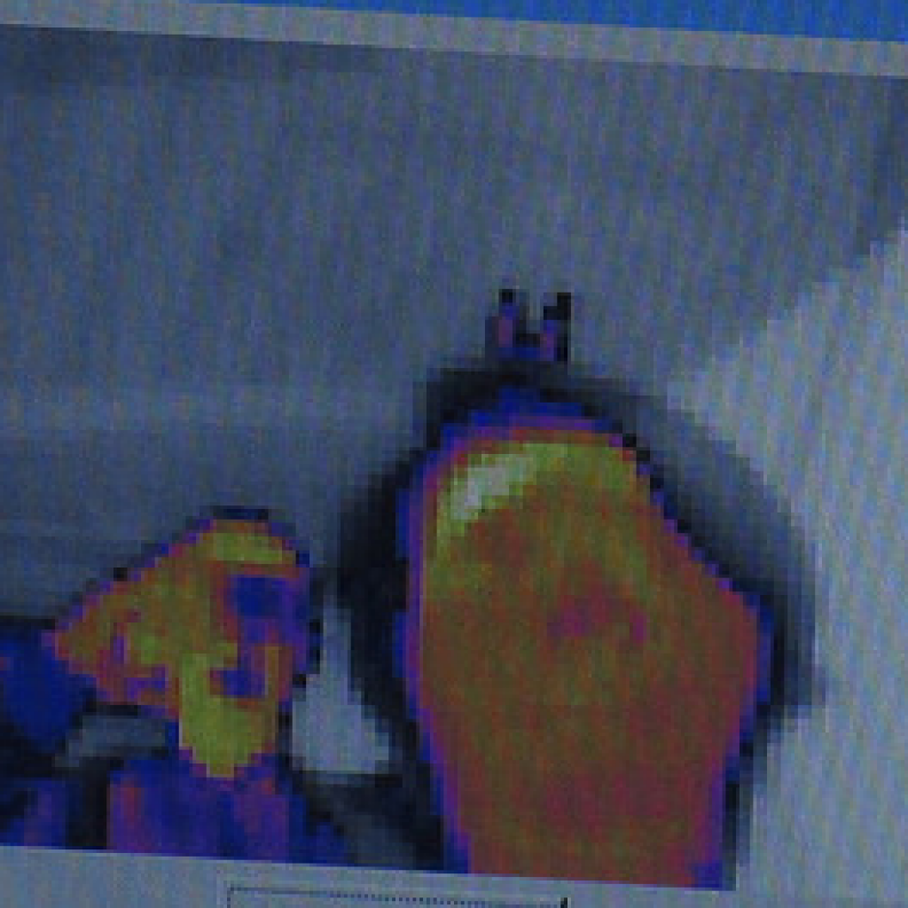
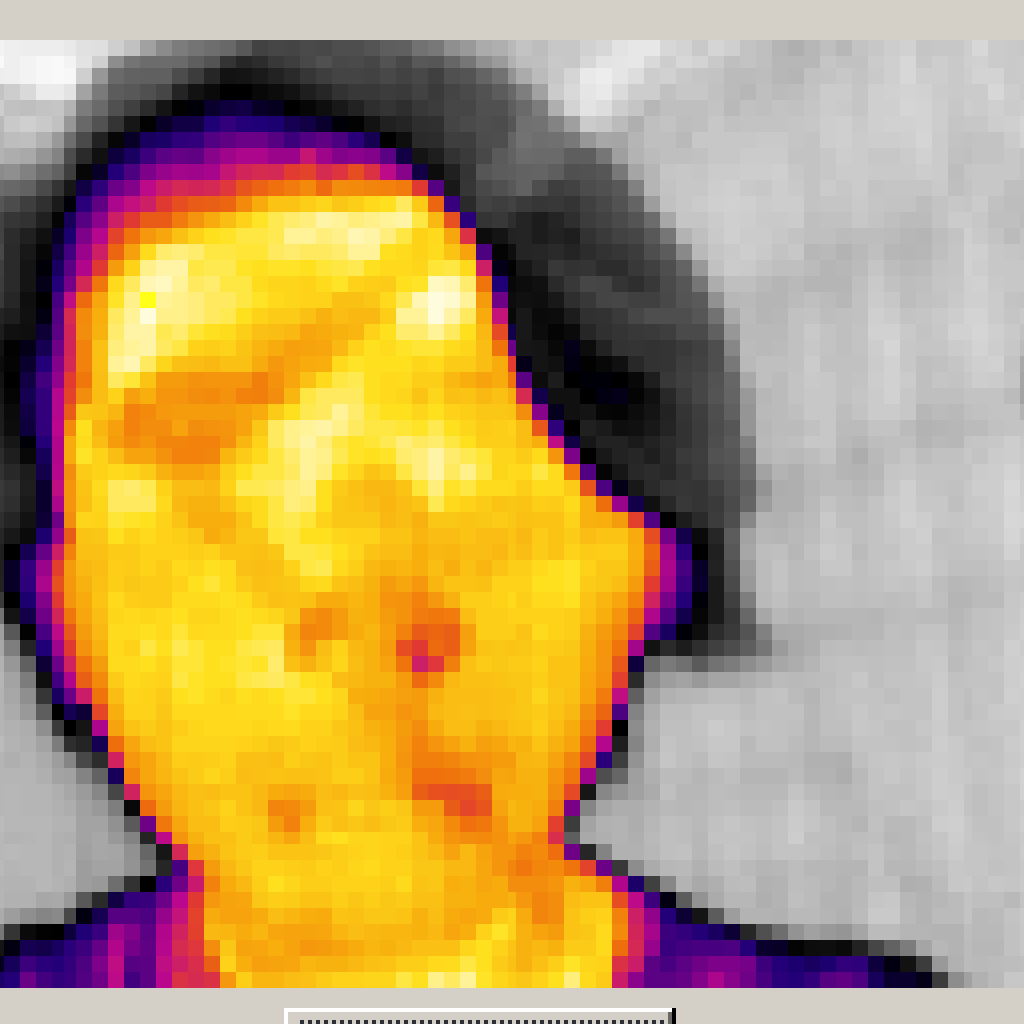
A Thermal-Imaging camera is a camera that detects the heat signature of objects and displays the difference with a set of colors relative to the temperature of the object.The Do-It-Yourself Thermal-Imaging camera uses a shuttered Lepton2.5 to sense infrared waves. The code of the camera is run by the Teensy 3.6 microprocessor.
Engineer
Raymond Chen
Area of Interest
Electrical Engineering
School
Lowell High School
Grade
Incoming Sophomore
Reflection
Throughout this program, I learned to compromise in case of emergencies. Four and a half weeks into working on my original camera I was dismayed to find that the microprocessor I used for the camera could not connect to a desktop. I worked for two days trying to get the microprocessor working but to no avail. I had almost completed work on the hardware of the project, but without the software, nothing would be able to work. I did not have enough time to reorder almost all of the materials and finish the project, so I was very unsure of what I could do. A Raspberry Pi ended up as the solution to most of my problems and the core of the replacement of my project. I still managed to build some form of a thermal viewer and can still improve off of it. Throughout the project I ran into many similar situations, and found some solution to each of them. This program has taught me that if there is something I can’t solve one way I must always try another.
Overview
Second Milestone
First Milestone
The first milestone was to get the shuttered FLIR to work as its own thermal-imager using a raspberry pi3 model b v1.2 and a lepton breakout board connected to an FLIR. The instructions for setting up the video are here: [goo.gl/rsrYQu]. I installed the entirety of the GitHub directory for access to all of the files within it. The Pi takes power from my laptop and displays onto the monitor. The process of getting the camera to work will require the internet, so I connected the Pi to a nearby wifi hotspot. When I was instructed to apply [make] from [LeptonSDKEmb32PUB] within the [raspberrypi_video] directory I could not find the file. I ended up finding [LeptonSDKEmb32PUB] within the [raspberrypi_libs] directory. Upon completing the setup, I discovered that the red rectangle that indicated that the FLIR was not connected was showing on the video screen. After repeatedly attempting to place the FLIR in the “perfect” position I found that there was no difference made, so I found help at [https://groups.google.com/forum/#!forum/flir-lepton] or [goo.gl/fSU3tD]. I dug through the forums to find a solution. I tried everything that was found to already have been a solution. I happened upon [https://groups.google.com/forum/#!searching/flir-lepton/jimmy$20t%7Csort:relevance/flir-lepton/qnS8OjmFo6I/Q2Fo9UrZNlsJ] and discovered that the conversation held the solution to my problems. I first attempted moving the MOSI pin to ground, but no change occurred so I returned everything to its original position. I then moved the CS pin from pin number 26 to pin number 24. The camera briefly started up, but when I picked the camera up, the reset disconnected and the video stopped working. I switched out the CS cable I was using, for I had found that the head was very loose, and replaced the wire with a new one. After some fidgeting, I managed to get the video to start again. The heat sensor was working, but it always held an afterimage of anything it detects after a number of resets. Even so, the video still works. The video that was taken only detects what was warmest within the room.
Starter Project
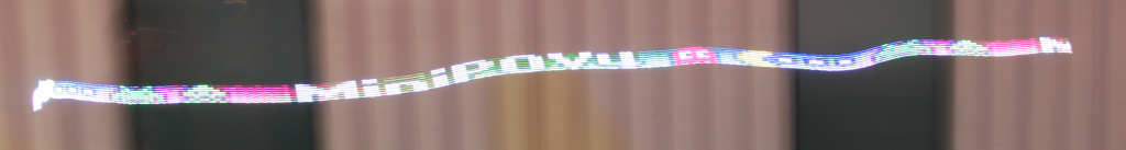
MiniPOV4

Overview
My name is Raymond, and I am a sophomore from Lowell high school. My starter project is the miniPOV, which is an acronym for “persistence of vision”. The device consists of eight light emitting diodes that flash a series of different colors that create images (This leaves a trail of letters that are much easier to visualize on camera than in person). The images displayed by the series of lights could be changed by accessing the microcontroller on the printed circuit board by plugging the miniPOV into a computer using a micro USB cord (The image displayed on the miniPOV is changed by using the sketchbook within the Processing software). The miniPOV can be tested using a camera (Have someone else record while you slide the device or vice versa). The Atmega328P-PU is the microcontroller that contains the programming for the miniPOV (The microcontroller is the small rectangular component on the circuit board). The small blue notch is the potentiometer or a variable resistor and it controls how quickly the LEDs flash and acts as an adjustable resistor. The resistors between the microcontroller and the USB jack are to allow the microcontroller to know that it is connected to another device. The two diodes next to the USB jack are the parts that stabilize the voltage and smoothens the transfer of voltage between the computer and the miniPOV. The small yellow pin next to the potentiometer is a ceramic capacitor. The ceramic capacitor helps stabilize the output voltage and filters out high-frequency noises so that the battery voltage can run smoothly. The small cylinders next to the ceramic capacitors are electrolytic capacitors, which smoothens both input and output voltage and removes low-frequency sounds. The microcontroller itself does not have the capability to send signals to all of the LEDs, so transistors are used to amplify its signal by a few hundred times. The resistors next to the transistors are used to reduce the voltage from the microcontroller so that it doesn’t overcharge the transistors. Next, there are the eight resistors above the LEDs and each is used to reduce the current flowing into the LEDs so that they don’t burn out as well as setting the brightness for the LEDs. The twelve megahertz crystal keep the LEDs flashing at a consistent rate and makes sure that the microcontroller runs at a certain rhythm. Each of the LEDs has four legs, three of which are for the colors red, green, and blue and the last one is for ground.
