Third Eye For The Blind
As engineering is such as powerful tool to invoke change in society, I knew that coming into Bluestamp, I wanted to build something that could help people. When I saw the opportunity to build a device that could help the blind community, I knew that was what I wanted to do. The Third Eye For The Blind is a device that makes use of an ultrasonic sensor and a programmed Arduino Board to sense when an object is in front of it. Depending what mode it is set to, it will either vibrate or make a sound to alert the user of an obstacle in their path.
Student
Pranav
Area of Interest
Bio-engineering
School
Wilcox High School
Grade
Incoming Junior
Final Milestone and Reflection
Final Build
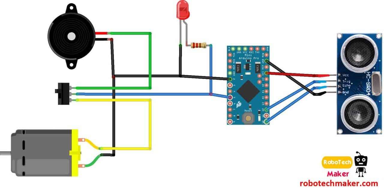
Circuit Diagram
Arduino Code
Bill of Materials
Build Plan
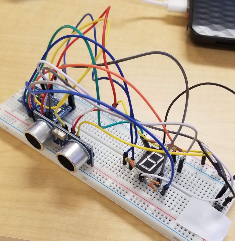
For my final milestone, I made a personal modification to my existing main build. In order give my project a use for a wider audience, I realized I could add a LED 7-segment display that returned distance in a number form depending on what the ultrasonic sensor detected (with the option to toggle between inches and centimeters). Surprisingly, this addition was not as easy as I originally thought it would be. I ran into several roadblocks along the way, some that were able to be fixed, but some that weren’t.
The first complication I ran into was with my design itself. I hadn’t anticipated this modification, and when mapping where my display would be added onto my existing build, I quickly realized that my Arduino Pro Micro did not have enough pins to power the old build and the LED Display. The Display needs 9 pins on its own, not counting the buttons used to trigger it. Therefore, I had to create an entirely new PCB system that was separate from my main build.
My next problem was with power. The Arduino sends out 5 volts, but that is too much for the display. Therefore, you have to have 7 resistors connected to each pin. There is no fixed or recommended value for resistors attached to a 7-segment display because there are so many types and models (common cathode, common anode) that it varies drastically. So when I connected 10K ohm resistors and the display barely showed up, I thought that it was a problem with the LED. After some experimentation, an easy fix was to lower the ohm resistance to about 300 ohms.
A new obstacle arose in the form of an Arduino glitch. At one point, my computer would no longer even sense that an Arduino was plugged in, which caused me to not be able to upload code to it. I ordered new Arduinos but the same thing happened. After some more research, I found out that I had “bricked” my Arduino by trying to upload my code to a 3.3V model when it was actually a 5V model. The fix was not as easy and required an hour’s worth of resetting the Arduino. When reset the Arduino would go into an 8 second bootloader mode. In these 8 seconds, you had the opportunity to upload the code, but if you went past that time, the program would crash. The timing of resetting and uploading was very precise and took several tries until my Arduino was working again.
My final issue came up when I moved all my new parts onto a PCB board. It was all good until the very end when I realized that I used faulty header pins that would not allow current to properly flow to the 7 segment display and thereby ruining my entire project. In the end, the time I had was too little and I had to move everything back onto a breadboard in order to ensure an at least partially completed modification.
In the end, it was definitely worth it coming up with a modification so that I could create a new aspect to my build and take its functionality to the next level. Through the numerous challenges that arose in my final milestone, I learned the value of double checking all my parts and keeping strict schedules so that everything is completed when it should be rather than rushing in the last minute. I viewed this as a culmination of all my other milestones as it took everything I learned in this process and presented itself in new challenges that I had to face using my knowledge.
Looking back on my four weeks at BlueStamp, I can’t believe how quickly the time flew by and how much I was able to learn in such a short time. Coming into BlueStamp, I literally had no knowledge of anything engineering related. Yet four weeks later, I have a completely working build of The Third Eye For The Blind and my own modification. This experience has proved to be invaluable as I learned not only engineering, but how to work independently and the value of persistence. Thanks to this program, I feel I have a firm stepping stone to start my own work in the world of engineering and a newfound passion for a field that will be useful and important wherever I go.
Third Milestone
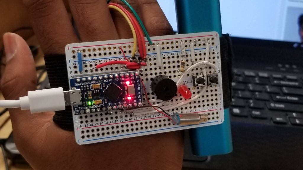
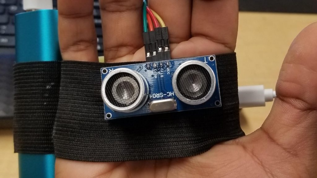
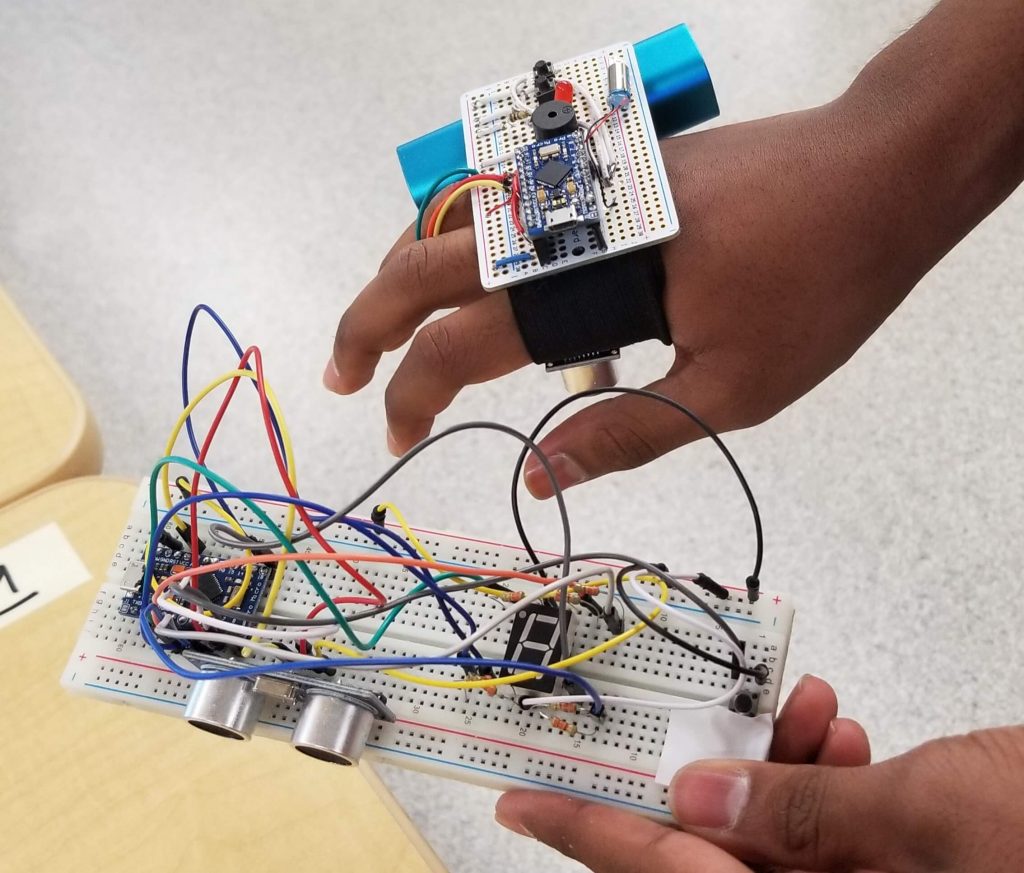
For my third milestone, I took two and a half week’s worth of prototyping on the breadboard and transferred it all onto a thinner and more compact circuit board. Afterwards, I moved that final circuit board onto a module that I could put on my hand and attach the battery pack to.
Before attempting to move anything onto my board, I decided to practice on a smaller circuit board with different components because my soldering was still a little shaky and it would be very inconvenient if I had to order a bunch of new parts simply because I messed up on soldering. As another precaution, I drew up a simple diagram on how my wiring would be on the final build so that I could quickly reference it when doing the soldering.
Although there weren’t too many software and physical modifications, one minor change in my build was my wiring. On a breadboard, there are special jumper wires that come in a standard size that you apply throughout the entire circuit that can be as spread out as you want. On my final build however, I quickly realized that because the board and solder joints were so tiny and close together, neatness would be crucial. Therefore, I took a couple hours just to measure out jumper wires and cut them into specific lengths so that the wires wouldn’t be all over the place and interfering with other ones.
Second Milestone

For my second milestone, I decided to build a fully working prototype of my main build. Using a breadboard, I implemented buttons, buzzers and a motor in order to give my project increased functionality. On the outside, my second milestone appears very similar to my first, but the major changes come from the code written into the Arduino.
Physically, the main additions to my breadboard are the two toggling buttons and the addition of a buzzer and motor. The buzzer works similar to the LED that was put in before, except it creates a sound as well. This function is especially important because as this device is made for the blind, only sounds can be perceived by the targeted audience. Additionally, if the beeping becomes too annoying, there is the option of switching to a vibration mode in which I have set a small motor to turn rapidly. This simulates vibrations and communicates the same distance alert as the buzzer would. These two components are coded to rapidly turn on and off. The closer the object is to the ultrasonic sensor, the shorter the intervals between the ons and offs are. Basic human instinct allows the user to translate the quickening of the beeps or vibrations as a message that an object is approaching.
One major obstacle that I faced was creating the code required to toggle between the vibration and sound mode. In my first trials, I was constantly getting confused because there were so many components that I thought I would have to code and control with the buttons. I decided to slow down and try using buttons on a simpler model. Once again, I went back to my basic LED example. After a while, I was able to get two buttons to toggle between two LEDs and realized that the task was not as complicated as I once thought. I went back to my breadboard, wired it, and implemented the same logic from the LEDs on a bigger scale. I set it up so that there was a boolean, and depending which button was pressed, it would change the state of the boolean to either true or false. If the boolean was false, it would trigger one function (the vibration), and if true, it would call the other mode (the buzzer sound).
Although it was one of the more tedious processes that I have had to work on, this milestone was unquestionably one the most crucial steps in my entire project. Now, all the hardware and software is set and the only steps remaining are to move it onto a more convenient PCB board.
First Milestone

Having been my first time working with Arduino and the ultrasonic sensor in general, I decided to make my First Milestone a little unrelated to my main project. I took a step back and spent a couple days researching Arduino, its code, and how circuits and the sensor worked.
The first part of my milestone involved creating a basic blinking LED circuit using the Arduino on a breadboard. Once I understood the basics of that, I moved on to wiring and programming the ultrasonic sensor, the primary component of my main build. After a lot of trial and error, I was able to build a working system in which the sensor sends out an ultrasonic wave, reads the time that the sound took to return, and formulates that into a measurable distance. I also used my newfound knowledge in LED circuits to create a system in which the LED would blink faster or slower depending on how close you were to the sensor.
Working with the breadboard and all the wiring that came with it was a new experience and a worthwhile challenge. I had several wires all over the place connected to my Arduino, LED, resistor, and ultrasonic sensor, and it was very easy to confuse the wiring and where each pin went. Eventually, I learned the importance of organization when wiring as it can save you hours in the long run. I decided to color code all the wires and keep a Notes document where I kept track of which system was connected to which pin number. Additionally, I realized the importance of comprehensively understanding every detail of your project. Originally, I used another person’s code for my build, but quickly realized that this limited my own understanding of the project, meaning I could not adjust it or debug it if something went wrong. Therefore, I remade the program, but took the time to understand what each command and line of code did the second time around.
Despite having to take a lot longer to master the Arduino Board, the sensor, and all the code, taking the process slow was definitely worth it as I now have a more thorough understanding of the parts that will ultimately become my main build.
Starter Project – Binary Blaster

My Starter Project was the Binary Blaster. This project involved a lot of soldering (and desoldering), along with learning the function of basic components in engineering such as resistors and capacitors.
Powered by two batteries and a pre-programmed microchip, it uses a 7 segment display, two switches, and four buttons to run a fun game teaching binary and hexadecimal. In order to make sure that the display and the button’s lights aren’t overloaded, we use resistors, a part that limits/halts the flow of current, to adjust the amount of current that can go through to them. Similarly, a capacitor, used to store and later give charge when necessary, slows down charge from the battery to keep the microchip stable. Finally, all the switches and buttons send input back to the microcontroller to run the final game.
A struggle in this project was definitely soldering. There were several pins in close bunches that required intricate soldering and it was a challenge to make sure that all of them were done properly.
One important thing that I learned was about current. At one point, I had two pins accidentally soldered together, and although I did not think it was that much of a problem, it turns out that because current takes the path of least resistance, rather than going the intended route, the current will instead travel over to the connected pin, resulting in a short circuit.