Introduction
Hello my name is Omar, I am a rising junior at Community Health Academy of the Heights. The projects I decided to build were the MintyBoost and the RC Hovercraft. I decided to build the MintyBoost because I figured that many people today have smart phones and they are always using it, just like me. It would be useful if I could have a portable charger that runs on double AA batteries and can charge many devices, so I came to conclusion that the Mintyboost would be my starter project. For my main project I wanted to build an aircraft but due to restrictions like the space I have in the room, I was not able to build it. Instead I moved on to the RC hovercraft. The RC hovercraft could hover on air and travel on water at a fast rate, and this brought my attention. Another thing about the hovercraft that amazed me was that I could work with electronics and mechanics, which are the types of engineering that I enjoy. My experience at BlueStamp Engineering was fun, I learned a lot while I was here. I had no real experience of engineering before BlueStamp. I learned how to make circuits, write code using an Arduino, work on my design skills and much more. In addition, BlueStamp made me more independent by solving problems on my own using creative thinking and researching up valuable resources instead of going to a instructor for information. It was fun attending 2015 BlueStamp Engineering and I am looking forward to join next year.
Final Milestone
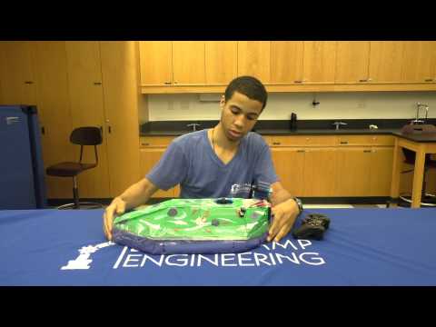
In my final milestone I present the last changes I have made since the second milestone. The photos below show a final product of my hovercraft and the circuits that are being used to control the electronic parts within the hovercraft. I have colored the hovercraft in green, white, red, and purple. I tried to color it similar to a military camouflage. I also made an opening in the middle of the hovercraft so it could be easier to take out my battery. Furthermore, I added Hobbywing stickers on the front and side of the hovercraft and as well as a Navy pin on the left side of the hovercraft. I did not add much changes into my hovercraft since it is in great condition. My goals for the hovercraft would to find a way to mount the skirt on the hovercraft and the motor in the middle without using tape.
Main Project (RC Hovercraft) 


Bill of Materials
Code Used on the Arduino
Second Milestone
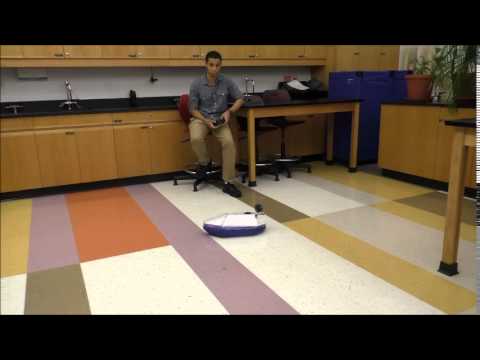
In my second milestone I demonstrate the different changes I have made on my hovercraft since my last milestone, which was my first one. In this milestone, I have a Playstation controller that sends signals to the Playstation receiver. From the receiver it goes to the Arduino which is a board that has code set up to make demands for my ESC’s (electric speed controllers). The ESC’s which control my motors, either telling it to speed up or slow down, could not be shown because they were under the depron foam. In addition, from the Arduino I could operate the servo which is beneath the motor that made the hovercraft turn. I have the servo in a sweep motion that sways from side to side, and with the help of the motor mounted on it, it is able to turn left and right through many angles. Moreover, in this milestone I display that the skirt of the hovercraft was mounted on to the actual hovercraft. The way the skirt works is that the air gathered from the motor in the middle inflates the skirt up essentially making the hovercraft “hover” or glide on air. Since this is my final product, I used my depron foam to make the dimensions of the body of the hovercraft. The problems I faced when developing this hovercraft was setting up code for the motors and connect it with the Playstation controller. This was the most difficult thing because I had no experience with coding at all. My goals for the future it to paint my hovercraft and figure out how to not use tape to mount my skirt on the hovercraft. Also I would like to have an opening to take out and place my battery at any moment since using tape to keep everything sealed would not be effective.
First Milestone
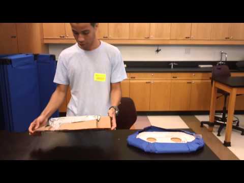
In my first milestone I speak about the model hovercraft that I built using pieces of cardboard. I talk about how the different parts interact with each other in order to make the hovercraft float on air, which essentially gives the name of “hover” craft. The different parts that were explained in the video were an ESC, a brushless motor, an Arduino, a breadboard, and my skirt for the hovercraft. The ESC stands for Electric Speed Controllers, and what this does in my project is that it determines the amount of voltage that is being sent to the motors controlling its speed at various moments. Furthermore, the brushless motors I have in my hovercraft are motors that turn due to the opposite poles within the magnets inside the motors and the coils. DC energy released to the coils makes them opposite to the magnet they face. In the milestone only one of the fans was shown (the one to make the model hover) because at the time I did not have a functional servo nor did I have code for my other motor. Moreover, these parts were connected through the Arduino and with the breadboard. The Arduino is a tool to produce code for parts like my ESC’s and my motors, making them able to cooperate with each other. In the Arduino, one sets up code for the electronics to perform operations by sending signals to them through the pins. The breadboard is used to connect multiple things in one pin, for example I had to use it for my ground in all my parts. Lastly the skirt that was shown in the video is to capture the air gathered by the motor and then lift up the hovercraft, making it float on air. In the future, I will make the servo operate while it is compatible with the the next motor that is going to mounted on the servo. With this the hovercraft will be able to turn in many directions. Also, I will start to build my final project or the final hovercraft, using depron foam.
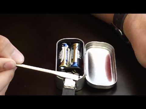
Starter Project
My starter project is called the MintyBoost. The purpose for the MintyBoost is to charge any device that can use a USB, for example, a phone, or an iPod etc. The MintyBoost contains several components. Its components are resistors, a PCB, capacitors, a diode, an inductor, a type A USB (female jack), a chip and chip holder, a battery box and two AA batteries. The way this project works is that the energy produced from the batteries is transferred on to the components on the PCB. The purpose of the chip is to produce an output voltage that is greater than the input so there can be enough energy transferred to the USB. The diode makes it possible to move the current away from the chip trying to protect it. Its purpose is to move current in one direction so it cannot interfere with the chip. The chip makes this possible by containing a circuit that has an electrical current around the capacitor. This circuit is opened and closed multiple times to trick the inductor to force a higher voltage on the capacitors. In order to do this the energy is stored into the capacitors in an electric field and into the inductor in a magnetic field. After the energy and voltage are transferred onto the capacitors they can be transferred onto the connected device and charge it. Each battery has a voltage of 1.5 volts, which is a total of 3 volts. It takes 5 volts to power up any devices that use a USB so the MintyBoost can range from 3 – 5 volts. This is enough to boost the energy of a device that is powered by a USB.