Remote Controlled Car
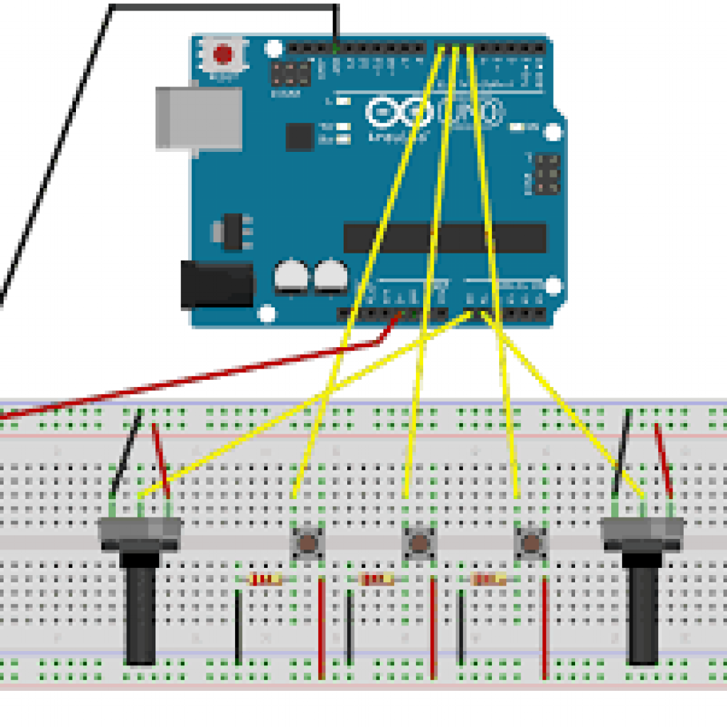
My project is a button controlled robot car. The robot responds to signals from three buttons, prompting it to move depending on the button.
Engineer
Noe ZR
Area of Interest
Biomedical Engineering
School
Marble Hill School for International Studies
Grade
Incoming Senior
Final Milestone
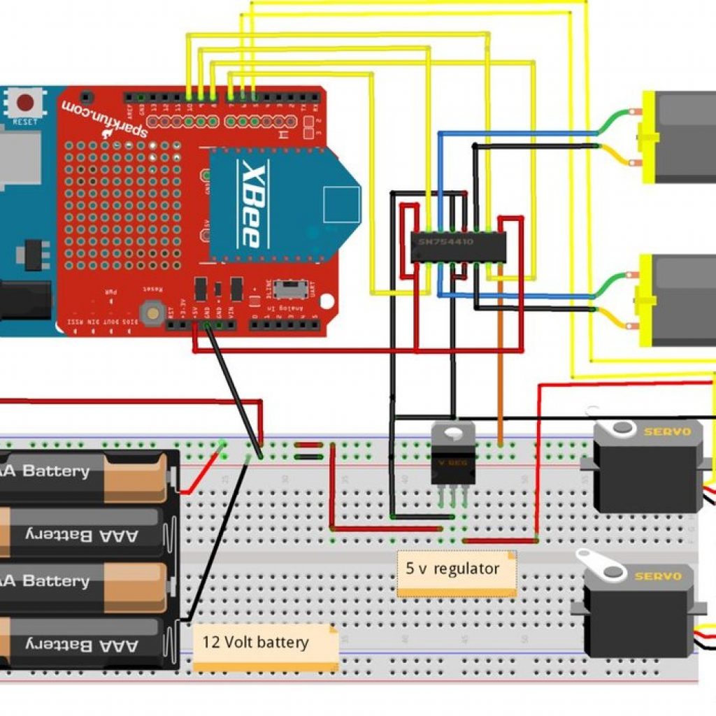
For my second milestone, I managed to establish basic XBee to XBee communication.
This portion of my project was important in order to establish a connection between my flex sensor glove and claw/wheels of the car.
Like my previous milestone, I was unaware of what to do. I struggled to find an application to establish a connection. After a couple of hours of looking for instructions, and downloading incorrect applications, I eventually found a website that told me what to do.
I then downloaded the XTCU application and followed the directions given to me.
Despite this, I struggled to connect more than one XBee because I tried to connect both XBee to a single XBee explorer. I kept receiving serial port errors, and after a while, I realized that my problem was not having a second XBee explorer.
After getting a second explorer my problem was not having USB ports on my computer, but that was solved with a simple USB adapter.
When I solved all these issues I was able to establish wireless connections between both XBee.
After getting a second explorer my problem was not having USB ports on my computer, but that was solved with a simple USB adapter.
First Milestone
Starter Project
String inputString = “”; // a String to hold incoming data
boolean stringComplete = false; // whether the string is complete
int ena=3;
int n1=4;
int n2=5;
int n3=6;
int n4=7;
int enb=11;
void setup() {
// initialize serial:
Serial.begin(9600);
// reserve 200 bytes for the inputString:
inputString.reserve(200);
pinMode(ena, OUTPUT);
pinMode(enb, OUTPUT);
pinMode(n1, OUTPUT);
pinMode(n2, OUTPUT);
pinMode(n3, OUTPUT);
pinMode(n4, OUTPUT);
}
void loop() {
analogWrite(ena, 255);
analogWrite(enb, 255);
// print the string when a newline arrives:
if (stringComplete) {
if(inputString==”f”){
forward();
}
if(inputString==”l”){
left();
}
if(inputString==”r”){
right();
}
if(inputString==”s”){
stop_now();
}
Serial.println(inputString);
inputString = “”;
stringComplete = false;
}
}
void forward(){
digitalWrite(n1, HIGH);
digitalWrite(n2, LOW);
digitalWrite(n3, HIGH);
digitalWrite(n4, LOW);
}
void left(){
digitalWrite(n1, HIGH);
digitalWrite(n2, LOW);
digitalWrite(n3, LOW);
digitalWrite(n4, HIGH);
}
void right(){
digitalWrite(n1, LOW);
digitalWrite(n2, HIGH);
digitalWrite(n3, HIGH);
digitalWrite(n4, LOW);
}
void stop_now(){
digitalWrite(n1, LOW);
digitalWrite(n2, LOW);
digitalWrite(n3, LOW);
digitalWrite(n4, LOW);
}
/*
SerialEvent occurs whenever a new data comes in the hardware serial RX. This
routine is run between each time loop() runs, so using delay inside loop can
delay response. Multiple bytes of data may be available.
*/
void serialEvent() {
while (Serial.available()) {
// get the new byte:
char inChar = (char)Serial.read();
// add it to the inputString:
inputString += inChar;
// if the incoming character is a newline, set a flag so the main loop can
// do something about it:
}
stringComplete = true;
}
int ena=3;
int n1=4;
int n2=5;
int n3=6;
int n4=7;
int enb=11;
void setup()
{
pinMode(ena, OUTPUT);
pinMode(enb, OUTPUT);
pinMode(n1, OUTPUT);
pinMode(n2, OUTPUT);
pinMode(n3, OUTPUT);
pinMode(n4, OUTPUT);
}
void loop()
{
digitalWrite(n1, HIGH);
digitalWrite(n2, LOW);
analogWrite(ena, 80);
digitalWrite(n3, HIGH);
digitalWrite(n4, LOW);
analogWrite(enb, 80);
delay(1000);
digitalWrite(n1, LOW);
digitalWrite(n2, HIGH);
analogWrite(ena, 80);
digitalWrite(n3, LOW);
digitalWrite(n4, HIGH);
analogWrite(enb, 80);
delay(1000);
}
void setup() {
Serial.begin(9600);
pinMode(A1,INPUT);
pinMode(A2,INPUT);
pinMode(A3,INPUT);
}
void loop() {
if(digitalRead(A1)){
Serial.println(“l”);
}
else if(digitalRead(A2)){
Serial.println(“f”);
}
else if(digitalRead(A3)){
Serial.println(“r”);
}
else {
Serial.println(“s”);
}
delay(10);
}