Ball Following Robot
brief description
Engineer
Neha R
Area of Interest
Mechanical Engineering
School
Evergreen Valley
Grade
Incoming Junior
Final Milestone
Third Milestone
Second Milestone
First Milestone
Schematics
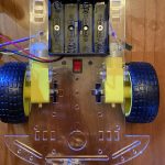
I had to build the chassis on my own because the version was older than most. It includes a switch, two wheels, two motors, adn a 6V battery pack.
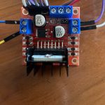
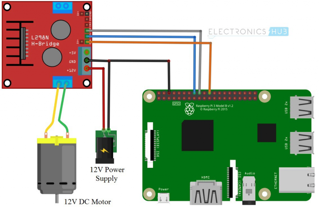
This is the L298N motor driver, which acts as a connection between the motors and the raspberry pi. It connects a positive and ground wire to the 6V battery pack on the robot. It also connects each motor to two output pins each. Then, there are the ENA and ENB pins that connect to the raspberry pi and control the speed of the motor. The IN1, IN2, IN3, and IN4 pins control the directions of the motor.
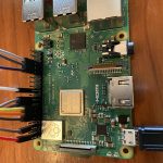
For my first milestone, I focused on the hardware side of the project. I started by setting up my Raspberry Pi and imaging the RaspberryPi OS onto the SD card. Then I built my chassis with its two motors. When I had a fully built chassis, I began the electrical work. I began by familiarizing myself with the LN298 motor driver and with its schematics. When I was done with that, I connected the motor driver to the battery, and the motor to the motor driver. Then, I did the most important connections: the motor driver to the raspberry pi and the ultrasonic sensors to the raspberry pi. To avoid a connection between a plug point and the raspberry pi, I used a power supply. Now I was done with the hardware side of the project. To set up for my second milestone, I got ssh working from my computer to raspberry pi, and familiarized myself with Linux commands and the vi editor.