Nathan A.
Hi, my name is Nathan and I go to The Birch Wathen Lenox School. For my year one main project I chose the NFC Computer Unlocker. I decided on doing this project because I constantly get tired of typing my computer password in. My year two intensive project is the Robotic Hand Controlled by a Glove with Arduino. I chose this because it is a much bigger challenge compared to what I did last year.
Engineer
Nathan A.
Area of Interest
Computer Science
School
The Birch Wathen Lenox School
Grade
Rising Junior
Final Milestone (2018)
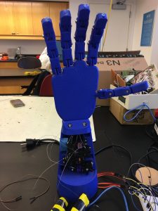
For my third and final milestone, I connected servo movement to the fingers , as well as set the flex sensors up to the glove. I made this connection with fishing wire. The fishing wire is there because as the fish wire is pulled down, the fingers get pulled down with it. To do this, I put the fish wire through the tops of each finger and hot glued them down to prevent slipping. To see the picture, see figure 2. I also wrote code to set the servos to zero rotation and one-hundred eighty rotation.
![]()
![]()
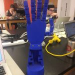
The code above is just to check that the fingers have full range of motion. This code was written by me so the servos were calibrated to the point where the fingers would go all the way up, and then all the way back down. I set it by checking the positions of the flex sensors when they were flexed and when they were straight. This was so that the finger positions would be calibrated correctly with each finger. The biggest problem I had with this part was that the fish wire would get caught on one of the servos and lost its grip on the glue, which caused the wire to slip. The wire slipping made the finger not move. There was no real solution to this problem, except to use some tape to prevent the wire from catching on the side of the servo. See figure 2 for the picture. After I finally got the fingers working, the next step was to set up the glove. In the future I will sew the flex sensors on to the glove, but for now I used electrical tape to hold the flex sensors on the glove temporarily for prototyping. For an image of the glove, see figure 1. In the process of doing this project, I learned more about electrical engineering. I also learned that the servos are very annoying to work with, as well as fishing wire. I also learned that electrical tape is useful for holding flex sensors onto gloves for a temporary period of time.
#include <Servo.h>
Servo finger1, finger2, finger3, finger4;
int servoPin1 = 5;
int servoPin2 = 6;
int servoPin3 = 9;
int servoPin4 = 10;
//Comment one of these out to switch between 0 and 180
//False = 0, True = 180
//bool idk = true;
bool idk = false;
void setup() {
// put your setup code here, to run once:
finger1.attach(servoPin1);
finger2.attach(servoPin2);
finger3.attach(servoPin3);
finger4.attach(servoPin4);
pinMode(servoPin1, OUTPUT);
pinMode(servoPin2, OUTPUT);
pinMode(servoPin3, OUTPUT);
pinMode(servoPin4, OUTPUT);
}
void loop() {
// put your main code here, to run repeatedly:
while(idk == false){
finger1.write(0);
finger2.write(0);
finger3.write(0);
finger4.write(0);
}
while(idk == true){
finger1.write(180);
finger2.write(180);
finger3.write(180);
finger4.write(180);
}
}
Figure 1: The glove with Electrical Tape
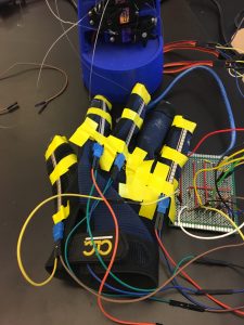
Figure 2: The hand with tape and glue
Reflection
For my year 2 portion of the program, I made an Instructables page, so that others can view and do the project as I have. The link to that Instructables page can be found here.
This year at Bluestamp, I challenged myself with a project focused on hardware and less on software. I am good at programming, so challenging myself like this seemed like a good idea. I feel because of this I learned more than I would have if I had done a project based on software. For example, I learned that when using two different power sources, the ground must be connected. Had I done a programming-based project, I would not have learned that. When I get the chance, I will sew the flex sensors down, and also make the project bluetooth enabled. Given the chance, I would definitely do this program again because of how the instructors make the students learn on their own, instead of doing every step for them. If I come back next year, I will want to do a project that is difficult, like the project I did this year, but more based on programming. In the future, I may want to be a computer scientist, but that does not mean that the electrical and mechanical engineering I learned will not be useful to me.
Second Milestone (2018)
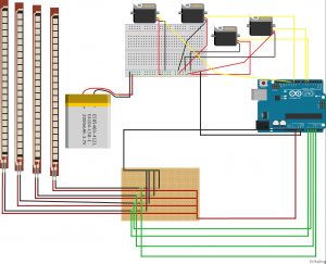
My second milestone was getting the servos to rotate with the bending of the flex sensors. I put the servos into the base of the arm and then soldered the circuit to a perfboard. For the circuit that connects the flex sensors to the servos, see figure 1. The four flex sensors send the signal to the analog pins A0, A1, A2, and A3 on the Arduino. The code interprets the input of the analog pins and through the digital pins 5, 6, 9, and 10, sends the signal to the servos to turn a certain amount, as seen here:

Looking at the digital pins, all four are PWM pins. PWM pins, or Pulse Width Modulation pins, are used to get an analog output through the digital pins. The code that reads and sends the signal for a flex sensor is
![]()
I wrote similar code the other flex sensors. The code that sets the positions to be related to the flex sensors, with similar code for the other ones.
![]()
The code that tells the servo how much to rotate, depending on the value of the position variables, with a similar code for the other three.
![]()
First, the code connects the digital and analog pins, as seen here:
![]()
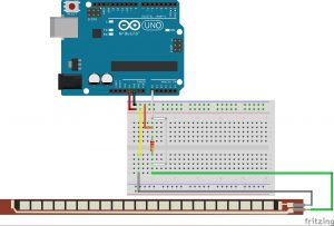
I wrote the codes to the other three similarly to this one. The biggest challenge I faced was soldering the circuit onto the perfboard. This was because the circuit on the first perfboard I used did not work, and after removing it and trying again, I ran out of room. On the new perfboard, I also had troubles, but I fixed them by connecting the ground of the breadboard to the ground on the Arduino. This milestone taught me more about electrical engineering because I learned that an entire circuit must have a common ground. I wired it with a voltage divider because the voltage going back into the Arduino from the flex sensor lets the Arduino know how bent the flex sensor is. The equation is VFlex = VIn ( RFlex / (RFlex + RΩ)) where VFlex is the degree to which the flex sensor is bent, VIn is the voltage supplied to the system, RFlex is the resistance of the flex sensor, and RΩ is the resistance of the resistor. VFlex and RFlex are variable, and VIn and RΩ are constant. The equation is used by the Arduino to find how bent the flex sensor is so the servos can rotate accordingly. See figure 3 for a voltage divider. To read more on voltage dividers, click here.
Figure 1: A diagram of circuit used can be seen
//Code is from dschurman on instructables.com
//Define sensors and servos
#include <Servo.h> //Includes servo library
Servo finger1, finger2, finger3, finger4;
int servoPin1 = 5;
int servoPin2 = 6;
int servoPin3 = 9;
int servoPin4 = 10;
int flexPin1 = A0;
int flexPin2 = A1;
int flexPin3 = A2;
int flexPin4 = A3;
void setup()
{
//Attach the servo objects to their respective pins
finger1.attach(servoPin1);
finger2.attach(servoPin2);
finger3.attach(servoPin3);
finger4.attach(servoPin4);
/* set each servo pin to output; I’m not acutally sure if this is
even necessary, but I did just in case it is */
pinMode(servoPin1, OUTPUT);
pinMode(servoPin2, OUTPUT);
pinMode(servoPin3, OUTPUT);
pinMode(servoPin4, OUTPUT);
//Set each flex sensor pin to input: this is necessary
pinMode(flexPin1, INPUT);
pinMode(flexPin2, INPUT);
pinMode(flexPin3, INPUT);
pinMode(flexPin4, INPUT);
}
void loop()
{
//Defines analog input variables
int flex1 = analogRead(flexPin1);
int flex2 = analogRead(flexPin2);
int flex3 = analogRead(flexPin3);
int flex4 = analogRead(flexPin4);
/* Defines “pos” variables as being proportional to the flex inputs.
The 400 to 700 value range seemed adequate for my sensors, but you can change
yours accordingly. */
int pos1 = map(flex1, 400, 700, 0, 180);
pos1 = constrain(pos1, 0, 180);
int pos2 = map(flex2, 400, 700, 0, 180);
pos2 = constrain(pos2, 0, 180);
int pos3 = map(flex3, 400, 700, 0, 180);
pos3 = constrain(pos3, 0, 180);
int pos4 = map(flex4, 480, 640, 0, 180);
pos4 = constrain(pos4, 0, 180);
//Tells servos to move by the amount specified in the “pos” variables
finger1.write(pos1);
finger2.write(pos2);
finger3.write(pos3);
finger4.write(pos4);
}
Figure 3: A diagram of a voltage divider with a flex sensor
First Milestone (2018)
My year two intensive project is the 3D printed robotic arm controlled by a glove. The original design is by Instructables user dschurman. A link can be found here. My first milestone was assembling the hand itself (figure 3). To do this, I had to separate all of the pieces. I then had to find which pieces went to each finger, and then screw them in. A problem I had was connecting the palm to the base, as the screws were not long enough to go all the way through. This problem was solved by the way the hand was printed. There was a little lip, holding the screws in place. Something I could have done better was the order I put the pieces in when assembling the hand. If I had switched two of the pieces, the fingers would be able to straighten out more. Specifically the piece open on two sides (figure 2) should be on the bottom, and the piece open on one side (figure 1) should be in the middle.
During this milestone, I learned that even though the pieces are all used, the order they are used in makes a difference. My next milestone is controlling the servos with the flex sensors. To do this, I plan on testing them outside of the hand, then attempting while they are in the hand.
Figure 1: A piece open on one end
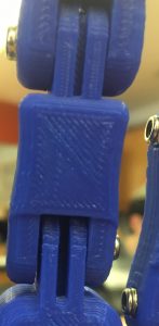
Figure 2: A piece open on both ends
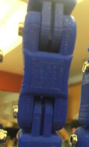
Figure 3: The hand
Starter Project (2018)
My year two starter project at Bluestamp Engineering in New York City was the Binary Blaster by Sparkfun, a game that teaches Binary as numbers. It works by showing a number on the two displays, then a user has to press buttons to match the number. The components are the buttons, speaker, capacitors, microcontroller, and switches. The four buttons represent Bit 0, 1, 2, and 3. Bit 0 represents 1, when it is on. Bit 1 represents 2, when it is on. Bit 2 represents 4, when it is on. And bit 3 represents 8, when it is on. While any of them are on, then the system adds whatever number is represented, so having all of them off except for Bit 2 would result in 4. Normally, we organize our numbers in base 10 or decimal format, but this is just a different way of representing numbers. If you want to read more, click here. The speaker is the part that makes noise if the user gets a correct answer. The capacitors store electricity to stabilize the power output. The microcontroller holds the programming for the behavior of the system. The microcontrollers controls the numbers on the display, as well as lighting the buttons up at the correct times. One switch is the power switch, and the other switch is the sound switch, which lets users decide if they want to use sound. There are two AA batteries which power the device.
A problem I faced was the leads on the buttons were very flexible. Two of the leads did not go through the proper holes on the board, causing those two buttons to not work. I had to use tweezers to pull the leads into the correct holes. While doing this, I learned how to look for a new angle for some problems. I also learned how to count in binary.
Final Milestone (2017)
My final milestone was creating a case, adding a picture feature, and adding a joystick. To do the picture I learned how to use homebrew to install terminal addons. To do the joystick I had to learn how to wire the joystick, how to code it, how to use state machines, and how to read the readings on the joystick. I had the difficulty of not having the proper size on my case, so the case was too big.


Reflection
My favorite part was the actual coding of all of the parts. The fact that I have a working project will all of my modifications feels good, as does the fact that I did this work myself. In the future I would like to wire LEDs into the case. I learned how to solder, code in c++, and wire a circuit. I learned that I am able to focus on something I enjoy doing. The process started with soldering some header pins onto the shield. Then I actually had to code the Arduino to do my passwords, and then add more passwords. I then started the mods. My first mod was adding lights via a breadboard. I had to code the lights to turn on and off. My second mod was a log of when the card is used. For that I had to learn how to use terminal for date and time. My third mod was taking a picture whenever the card was used. For this I had to install homebrew to install another file for taking a picture. My fourth and final mod was adding a joystick which acts as a two step verification before accessing the computer. For this I had to wire the joystick and learn how to code it.