
Hi! My name is Michelle. I am a rising sophomore at Greenwich High School. When I first heard about Bluestamp, I was so excited to have the opportunity to expand upon my interest in engineering. After six weeks of Bluestamp, I have learned so much about being independent and solving my own problems. After building two amazing projects, I have learned so much about what it means to be a real engineer.
For my starter project, I made a light organ. I chose this project because I like music and I thought it would be cool to make a beautiful array of lights respond to sound. I learned a lot about the basic electronic parts and how to solder. My main project was a clock that wirelessly syncs to the atomic clock. This project interested me because I have seen these clocks around but always wondered about how they worked. I thought that it would be cool to make my own super accurate clock. I’ve always wanted a clock that would always be accurate, and now I have one!
Overall, I’ve really enjoyed my past six weeks at Bluestamp. My experience at Bluestamp has made me realize that I enjoy engineering a lot. I love thinking of something that I want to build and then actually making it happen. This summer has really opened my eyes to a real engineering experience. I was introduced to both electrical engineering and programming. I now know that I enjoy both of these, and I want to pursue them further in the future. I’m so glad that I chose to spend my summer persevering through the challenges of engineering at Bluestamp!

Final Project: A Fully Functional Atomic Clock with Alarm in Case!
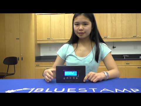
I’m so excited that I finished my final project: a fully functional, extremely accurate alarm clock that syncs to the WWVB signal! To finish my project off, I had to put my alarm clock inside of the project box that I purchased. This may sound like a simple task, but it was actually surprisingly difficult. To begin, I had to cut holes for the LCD and buttons in my box. Considering the fact that my box is made off thick plastic, I had to use a Dremel to cut the hole for the LCD and a drill to make the holes for my buttons. At first, I was planning on 3D printing my box, but I ended up deciding to buy a project box instead because of the issues with the 3D printer.

To put the square buttons in, I needed to make holes, but as I found out, it is quite difficult to make a rectangular shape with a drill, so I had to spend a lot of time starting out with a big drill bit and then using a smaller one to make the corners of the button fit.
Once I finished cutting the holes for the LCD and buttons, I was faced with the challenge of gluing them in. This proved to be challenging because of a couple of different reasons. First of all, the holes were just barely big enough to fit the buttons into. Secondly, my perf board was densely packed with wire leading in all directions, so it was quite challenging to angle it in a way that would not cause the wires to snap or break when I closed the box and made the connections. When I finally finished hot gluing all the buttons and the LCD, I had to face two more problems: how to power the clock and how to make everything fit inside of the box.

To power the clock, I settled on using portable battery charger meant to charge a phone. The first charger that I got was a “smart” charger. This means that when it thinks that a phone is done charging (or not charging), it will turn off to prevent a phone from frying. The problem was that the Arduino wasn’t pulling enough voltage from the “smart” charger, so it didn’t recognize that anything was charging from it and turned off. To solve this issue, I had to use a cheaper, less fancy portable charger that didn’t have the automatic turnoff.
Fitting everything in the box was also a key issue that I had to surpass. In the process of fitting things into the box, the stiff wires that I was using kept snapping and breaking. I was constantly resoldering wires onto the perf board or extending wires. To fix this, I changed some of the wires from the stiff wire to jumper wires. I also just have to be very careful in the future to make sure the wires don’t continue to break.
Milestone 3 of Main Project: Getting my Alarm Clock Working!
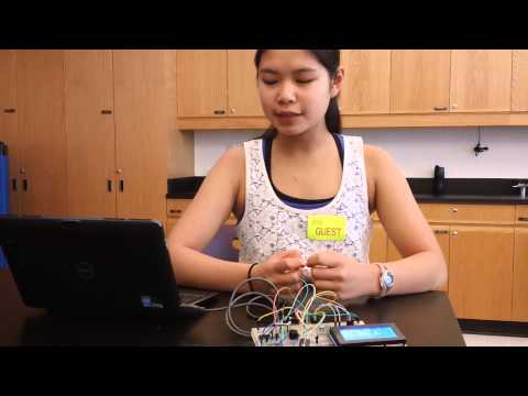
My third milestone was adding the alarm clock to my clock. To achieve this, I had write the code for the buttons, the buzzer, and the alarm itself. To use my alarm clock, I use the buttons to set the alarm. When the values set by the buttons are equal to the current time, my buzzer goes off. I have four buttons which control setting the hour of the alarm, setting minute of the alarm, whether the alarm is on/off, and turning the alarm off. In my code, I have it so that if the time matches and the alarm is on, then the buzzer will go off until the off button is pressed.

Initially, the alarm would only work for the first few minutes after I turned on the clock. To fix this problem, I went back through the code and looked for any potential errors that would impact whether or not the alarm worked for larger values. I realized that I didn’t have the times all in decimal, so unless it matched in binary, it wouldn’t work. Once I changed the binary to base 10, the problem was solved.

My third milestone breadboard
I also had a hard time getting the buttons to only increment by one every time the button was pressed. At first, when I pressed the button once, the value would go up by 10-15 numbers because it was constantly incrementing the value when the button was pressed. I changed my code by making it so that it would only increment if the state of the button had changed. This means it would only add if the button went from unpressed to pressed.

My third milestone schematic
Milestone 2 of Main Project: Getting the RTC (Real Time Clock Module) and WWVB Receiver Working
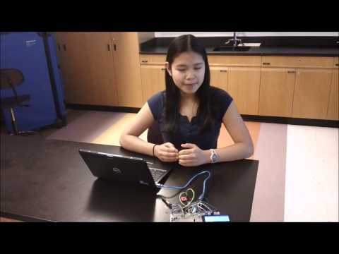
After a lot of hard work, I got my RTC and WWVB receiver working. Now, I have a fully functional, extremely accurate clock! My clock works by receiving a signal from the WWVB receiver and then decoding this signal into a binary time. Next, code which I wrote turns this UTC into EST time. Then, my new time is sent to the real time clock module (RTC). The RTC is updated every time a frame (WWVB signal) is received. The WWVB signal is broadcast from the atomic clock in Colorado, so this is what makes my clock extremely accurate.
Getting everything to work involved looking through a lot of code and troubleshooting. When I first opened the code for the WWVB receiver, I was completely overwhelmed with the 900 lines of complicated code. After many days of sitting down and looking through the code function by function, I began to understand how it worked. Even as I began to understand how the code received signal, kept track of time, and updated the RTC, my clock still displayed 165:165:165 for the time. For some reason, every time or date was set to 165. This puzzled me for days as it appeared that all the code was correct for pulling the date and time from the RTC using I2C communication (wire library). I also checked my circuit against my schematic; it seemed that everything was correct. Then, I realized that I had a revision 3 Arduino compared to the revision 2 Arduino that was used in the schematic I was looking at. In the Rev. 3 version of the Arduino, there are two separate pins specifically for I2C communication. When I moved my I2C communication pins to SCL and SDA instead of the analog pins (4&5), I was able to get the LCD to display a real time--even if it wasn’t an accurate one. My next challenge: getting the WWVB receiver to pickup & decode the signal and then update the RTC with the correct time.

My clock displaying the time & leap second state set by the WWVB signal
To do this, I had to first update the code since many of the functions had since been changed. After that, I looked through the code to determine if there were any mistakes in it. I found that since my WWVB receiver was different from the one that was in the schematic, I had no TCO pin--I only had an NTCO pin. The “N” in front meant that the signal I was getting was inverted. To fix this problem, I had to write code to invert the signal I received so that the code was able to decode it into a time that could be sent to the RTC. Before sending this UTC time to the RTC, I wanted to change it to Eastern Standard Time so that it wouldn’t be four hours off. To do this, I wrote my own code that subtracts four hours from the time received by the WWVB receiver. This was much more difficult than it seems because I had to take into account the possibility that subtracting four hours would have the possibility of going back a day, month, or even year. I had a really hard time doing this because I had to deal with the binary time. To change the date, I ended up incrementing the “doy” (day of year) variable if four hours subtracted from the current time was negative.
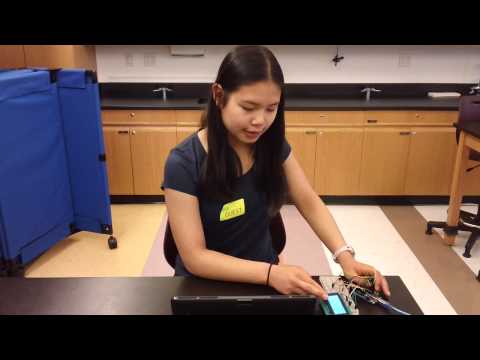
I went through many steps to troubleshoot my WWVB receiver. First, I used a DMM (digital multi meter) to make sure that both ends of the antennae were connected. Then, I used a digital oscilloscope to make sure that I was receiving some type of signal. I also inserted many debugging statements into my code so that I could figure out exactly what was working and what was not. After analyzing the debugging statements, I realized that my clock was not receiving enough signal where I was putting it, so I moved it to the west side (closer to Colorado) of my house. When I did this, my receiver was finally able to pick up sufficient signal to decode the time!

My clock showing the time & date from the WWVB receiver
I learned so much about both coding and how to troubleshoot. To achieve this second milestone, I had to do a lot of troubleshooting for my WWVB receiver. When I was looking through the code, I also learned about so many types of Arduino functions and syntax. I now know about using structs, pointers, case/switches, and so many other things! I’m really excited to apply everything that I learned to my modifications!
Check out my second milestone video above and my code (below)!
Milestone 1 of Main Project: Getting the LCD Working and Displaying Time & Date
I reached my first milestone of my main project! My main project is going to be a clock that automatically syncs to the atomic clock by receiving the WWVB signal. Finding this receiver was extremely difficult since it has been discontinued. In order to get a WWVB receiver, I had to take apart an atomic clock. This receiver had to be desoldered from the other clock. Upon observing the receiver, I realized that it was different from any receiver that I could find a schematic for. Because of this, it is going to very difficult to get the WWVB receiver working, so for my first milestone, I decided to start out by getting the LCD to print the time and date.
After many setbacks and challenges, I was finally able to connect my LCD successfully and make it display the time and date! To do this, I connected pins 12, 11, 6, 5, 4 and 3 on the Arduino to pins on the LCD using jumper wires. Each of these digital pins on the Arduino controls a specific pin on the LCD. Initially, I was working towards getting the LCD to display “Hello, World.” To achieve this, I had to overcome many setbacks and challenges. It was extremely frustrating while I was working on it, but in the end, it really paid off when I got it to work! I rewired my LCD and redid my entire circuit many times trying to figure out what was wrong with it. One issue was that I was initiating the incorrect Arduino pins. After fixing this, my LCD still wouldn’t write anything, so I decided to plug my LCD into a breadboard to make finding mistakes in my circuit easier. Even when I did this, my LCD still wouldn’t write “Hello, World.” After testing many different circuit arrangements, I realized that the potentiometer I was using was working incorrectly by checking it with a digital multimeter. After changing the potentiometer, the LCD lit up, but still wouldn’t print. To solve this problem, I had to adjust the potentiometer (which controls the brightness of the LCD), to make the words that the LCD was printing visible.

My LCD displaying a time and date that I set
After this, I wrote my own code to make the Arduino keep track of time. My code is based off the millis() function in Arduino, which keeps track of the milliseconds since my code was started. When I first started, I was using mod (%) to keep track of time, but decided to write function that added one second every second instead of dividing out the milliseconds since the start as a more efficient way of keeping time. (You can see the link to my code below). Finally, after hours of troubleshooting and changing the types of variables and order of my code, I got my Arduino to keep time!
In achieving this milestone, I learned a lot about how Arduino code works! This is really exciting because it will help me with completing my main project and is a really great introduction to computer programming! To achieve my next milestone, I will have to get my WWVB receiver and DS1307 RTC module working. This will be very challenging, but I’m really excited!
My First Milestone Code: Milestone_1_Code_Final
Starter Project: Light Organ
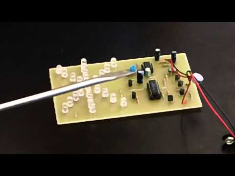
For my starter project, I chose to build a light organ. This is made up of 25 LEDs that respond to music. First, the microphone picks up sound. Then, the first 3 transistors increase the signal strength to the level needed to drive the sequencing display circuitry which is made up of IC1 and IC2. These 3 transistors are arranged in a direct coupled amplifier. This means that the output from the first transistor becomes the input for the second transistor, and so on. This makes the signal increase. When IC1 is turned on by an amplified sound signal, it outputs a series of clock pulses on pin 3. These clock pulses are sent to the Johnson counter IC2. Every time it receives a clock pulse on pin 14, it shifts or sequences its output to a different pin. These outputs are then coupled to each of the output transistors Q4 to Q7 in sequence. Each of these output transistors drives a group of 6 LEDs. IC2 also has one of its output pins tied directly to a dual element yellow LED that is the center of the LED display. A 9V battery supplies power.
The entire project is composed of 4 capacitors, 25 LEDs, 1 electret microphone, 2 horizontal trimmer resistors, 7 transistors, 11 resistors, 1 battery snap, an 8 pin IC socket, 16 pin IC socket and a PC board. Before this project, I didn’t know a lot about electronics, but while doing this project, I learned a lot about all of these electronic parts. I learned the purpose of resistors and how to read them. Resistors are meant to provide resistance in a circuit so that the current doesn’t get too strong. I also learned that capacitors store energy. LED stand for “light emitting diode.” This means that current only travels in one direction. It was very important that I made sure the LEDs were aligned correctly.
One problem I had was getting all of the lights to respond to the microphone. When I first finished soldering, the only lights that turned on were the yellow ones around the star. None of the other lights worked. To fix this, I went back and made sure all of my soldering points were good and that there was nothing connected that should not have been connected. When I went back and tried again, everything worked.
What do you mean “the arduino wasn’t pulling enough voltage” did you mean current?