
Table of Contents: •Final Milestone •Third Milestone •Second Milestone •First Milestone •Starter Project
My name is Michael, and I am a rising senior at Regis High School. During my time at BlueStamp, I built a Gram Piano Keyboard as my starter project and a Remotely Controlled Robot Tank for my main project. Before starting these projects, I did not have much experience working with electronic hardware, although I had experience with working with software and coding. Thus, I chose projects that would help me gain more experience with the physical side of electronics rather than just software. Ever since eighth grade, I have been teaching myself how to write code in various programming, scripting, and markup languages, including Java, HTML, PHP, Javascript, Python, and C++. In addition, my education at Regis has also helped me learn more about computers, such as how to work with databases, spreadsheets, and basic computer hardware. I also joined Computer Club at my school, which actually focused mostly on robotics and also general computer science. Within Computer Club, I have participated on teams in both the FIRST Tech Challenge, which is a robotics competition, and Cyberpatriot, which is a cybersecurity competition.
Overall, BlueStamp has not only taught important skills to me, but it has also introduced me to solving problems independently. When I encountered issues with building my tank, the instructors would only help me if I had researched the problem and made multiple attempts to solve it. In addition, my project allowed for multiple modifications because I completed the base project early. Thus, BlueStamp has also allowed me to use creativity when working on my project and to enjoy my progress.
RC Robot Tank

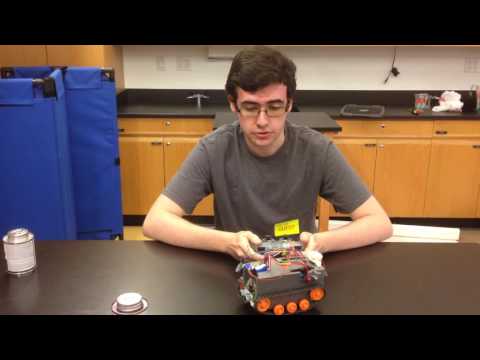
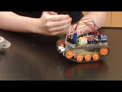
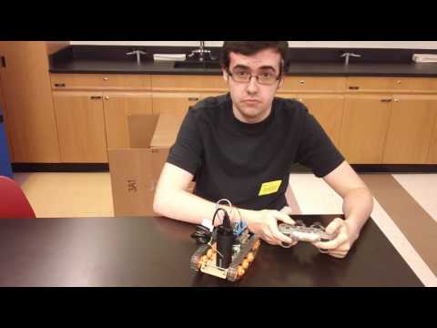
Above is a picture of the completed tank with all modifications (the ultrasonic sensor, status LED, buzzer horn, 7.4V battery, 6V DC motors, a depron case, and a laser diode attached to a moving servo motor) alongside the Playstation 2 Controller used. Click on the image to view a larger version.
- My Build Plan
- My Bill Of Materials (BOM)
- Download for My Schematic (requires Fritzing, or see Figure A. below)
- The final version of my code (text version)
Final Milestone
After finishing my third milestone, I found that I still had time to add more modifications to my project. To increase the tank’s stability, I created a case, which was made of depron foam, for my tank. In order to accomplish this, I first measured the dimensions I needed, which not only included the tank’s volume, but also the positions of the main wheels, components, and wires. I first made test cuts on thinner foam, and, after I decided which cuts I wanted to keep, I cut out pieces of the thicker foam that I wanted to use. I then glued my three pieces of foam (the two sides and the top) together once I positioned it correctly on the tank.
As another modification, I added a laser diode and a servo to the tank. In particular, this laser not only could act as a pointer, but could also be aimed at a target. By attaching the laser diode to the servo motor, which, unlike a DC motor, turns to a certain position (from 0 to 180 degrees), the tank can actually aim the laser vertically with the servo and horizontally by turning the tank. To use the laser and servo, I created new code. Now, when the user presses the square button on the PS2 controller, the laser diode turns on and the servo’s position can be increased or decreased slowly by moving the right analog stick upward or downward.
When I added the servo, I needed to use a digital pin that had been already been in use (pin 9). Thus, I needed to alter my existing code to utilize it without error. In addition, I found that many of my connections needed to be cleaned up so that the tank could work more reliably and appear more presentable. Therefore, I resoldered multiple joints and also used heat shrink tubes to better insulate some of my wiring. I also used zip ties to keep wires together and stable, adhesive pads to keep components, such as the ultrasonic sensor, attached, and duct tape for the tank’s power switch and the servo motor.
Code used for my final milestone can be found here.

Figure A. My schematic for my third milestone. Click on it to open the source image.
Download the Fritzing file here.
Third Milestone
For my third milestone, I added some of my own modifications to my RC tank and also improved its overall performance. First, I added a status LED to the motor shield so that the user can know which mode of control they are currently using. I connected the LED to a digital pin of the Arduino, then to a 560 Ohm resistor that leads to ground. In addition, I added a buzzer in a similar way, using another 560 Ohm resistor, so that the user can create a beeping sound that can act as a horn.
Additionally, I attached an ultrasonic sensor to the Arduino, which would allow for an autonomous mode. The ultrasonic sensor itself, via the trigger pin, sends out an ultrasonic wave that travels through the air and bounces off of the first object it hits. Once it bounces, the wave returns and the sensor indicates that the wave has returned to the Arduino via the echo pin. Thus, the Arduino is able to measure the amount of time it takes for the wave to return. Since the wave moves at the speed of sound, the Arduino can calculate an object’s distance from the sensor. Therefore, the Arduino was able to avoid obstacles. For my code, I added a new mode that uses the ultrasonic sensor in this manner. When the user presses the triangle button, the tank moves at maximum speed forward until the distance between an object in front of it becomes 10 centimeters or less. Then, the tank turns clockwise for 200 milliseconds and checks the distance again. If there is still an obstacle, it will keep turning. If there is no obstacle 10 centimeters or less away, the tank then moves forward again.
I also added another mode for controlling the tank that uses the left analog stick instead of just the directional pads. In this mode, the user can control the speed of the tank as well. The R2 button increases speed forward and decreases speed backward while the L2 button performs the reverse action. Based on the left analog stick’s position along the x-axis, the tank slows down the speed of one track relatively to the other to allow turning. In addition, I am using a new 7.4V lithium polymer battery for the tank now, as I am now also using motors rated at 6V instead of the original ones rated at 3V. Since this battery also provides greater current, the tank also performs better overall, as the Arduino would sometimes reset if too much current was being drawn (which would usually occur when the motors would begin to move in a certain direction).
When the controller is set to the initial mode (the mode for moving the tank using the directional buttons), the LED will blink once every second. If the controller is set to be controlled via the left analog stick, the LED blinks twice quickly every second. For the autonomous mode, the light stays steadily on. In addition, pressing the circle button causes the buzzer to turn on as long it is pressed.
When trying to integrate the tank’s new components, I faced a few challenges. For instance, I found creating code for the status LED more difficult than I expected, as the Arduino runs code line-by-line. Thus, if I attempted to add delays for the LED blinks, the Arduino would no longer be able to be controlled. To solve this problem, I added a counter within the code’s loop function (which I have set up to have a 50 millisecond delay each time it runs) so that it can effectively still incorporate delays at 50 millisecond steps. In addition, I also had to incorporate a counter in the code for the autonomous mode, as I found that turning the tank for a longer amount of time when facing an obstacle better helps the tank avoid it.
Code used for my third milestone can be found here.

Figure B. My schematic for my third milestone. Click on it to open the source image.
Download the Fritzing file here.
Second Milestone
For reaching the second milestone for my main project, I wanted to be able to control the tank with a wireless Dualshock PS2 controller. In order to accomplish this, I needed to connect the controller’s wireless dongle to the Arduino and motor shield. Initially, I tested the controller and the Arduino’s ability to receive input from the controller by detaching the Arduino from the motor shield and using jumper wires to temporarily connect the pins on the Arduino to the pins on the dongle. I used example code from the PS2X library to print out information to my computer based on output from the dongle to the Arduino. At first, the testing was unsuccessful as I confused some of the pins, but I fixed the issues and successfully read the controller’s button presses. I connected the clock (blue), command (purple), attention (yellow), and data (brown) cables to four of the Arduino’s digital pins (11, 12, 13, 14), and I also connected the power (red) wire to the 3V pin and the ground (black) wire to ground.
After these tests, I then soldered additional male headers to the Arduino motor shield so that I could connect the pins of the dongle to the motor shield and Arduino via female to female jumper wires. Once this was done, I then created my own code to actually move the motors based on the directional pad buttons. Pressing the upward or downward button causes the tank to move forward or backward respectively, while pressing the right or left button causes the tank to rotate clockwise or counterclockwise, which the tank accomplishes by moving one track backward and the other forward. If any of the directional pads are released, the tank stops moving. Thus, the user can hold down one of these buttons to continuously move until it is let go of. In addition, I also added the functionality to prevent the motors from moving by adding code that sets both motors’ speed to a value of 0 if the “start” button is pressed. If the “start” button is pressed again, the motors’ speed will be set to my default value of 255 (the maximum value) so that the tank can be used again.
When I began to test the new setup, I encountered a major issue in controlling the motors, which would start moving and stopping randomly. After many attempts at troubleshooting, I isolated the issue to the DC barrel jack on the Arduino. I learned that Arduino would keep resetting whenever too much current was drawn (which normally occurs when the motors first begin to move). Thus, I decided to power the tank with a USB connection instead of through the DC barrel. After I changed this connection, the tank began working properly, and I finally completed my second milestone.
Code used for the second milestone can be found here.

Figure C. My schematic for my second milestone. Click on it to open the source image.
Download the Fritzing file here.
First Milestone
For my first milestone, I set a goal of assembling the chassis of the tank and testing the motors using the Arduino with a motor shield attached. For my gearbox, I used a 114.7:1 gear ratio because I calculated that it would be able to support about two pounds of weight, which allows me to add more parts to this project while not sacrificing too much speed. In addition, I also researched the voltage and current requirements of my motors to make sure that my power source (a 5V/2.1A rechargeable battery) was compatible. While the motors have a recommended maximum of 3V, running at a higher voltage should only cause the motor brushes to wear down more quickly (especially if they are left on for too long). I also soldered the Adafruit Motor Shield v2.3 to the Arduino and I learned that I could power the shield, Arduino, and the motors with the battery alone by cutting the micro USB end of a short USB cable that came with the battery, stripping that end of the wire, and attaching the exposed positive and negative cables to a DC connector so that I could connect the battery to the DC barrel jack. I connected the two motors to two ports on the shield (the M1 and M2 ports). I then altered some existing example code from the libraries for the shield. This code causes the motors to move forward with increasing speed, then slow down with decreasing speed, then move backward with increasing speed, and then slow down to a stop. I uploaded the code to the Arduino and the tank moved forward then backward successfully.
Figure D. My schematic for my first milestone. Click on it to open the source image.
Download the Fritzing file here.
Starter Project
For my starter project, I constructed a Mini Piano Keyboard. For “keys,” this device utilizes capacitive sensors, which can detect key presses using the human body’s capacitance by measuring the time it takes for a signal from a receive pin to match a send pin (because of the RC time constant, capacitance can be determined from the amount of time if the resistance is constant). An Atmel Microcontroller measures the input received from these sensors and, with prewritten code, sends a signal to a PWM (Pulse-Width Modulation) Speaker to generate sound waves via a digital signal from the microcontroller. This project also makes use of a potentiometer to allow a user to select one of three octaves to play on by turning its knob to vary its resistance. In addition, a small button also can cause the microcontroller to play a short song from the provided code. The project also required various resistors to restrict the current so that no components would be damaged, capacitors to store electric charge, and two LEDs. One LED indicates that the device is powered, and the other indicates that the keyboard is ready to be played (blinking for half a second) or that a song is currently playing (staying on steadily).
Great job!