Melanie A.

Hi, my name is Melanie and I’m a rising senior at Lyons Community School. My intensive project, a smartwatch, was inspired by this instructable. I chose this project because I’ve gained an interest in wearable technology, and I wanted to work on a project that combined programming, electronics, and creativity.

Overall, I had an enriching experience at BlueStamp Engineering. Not only did I obtain new skills I will use later in my career as an engineer, but I also learned a lot  about myself. BlueStamp taught me that I can be humble while practing self-advocacy. I  also realize the importance of amplifying my voice in a field where few resemble me and my perspectives.

My next step in my project is to make it solar powered and continue adding on more features.

Engineer

Melanie A.

Area of Interest


Mechanical Engineering,

Robotics Engineering,

Computer Programming

School

Lyons Community School

Grade

Incoming Senior

Final Project

My final milestone was designing and 3D printing my watch base. This is an important aspect of my project because making the watch wearable and portable allows me to self-advocate by showing my project to everyone I meet. 

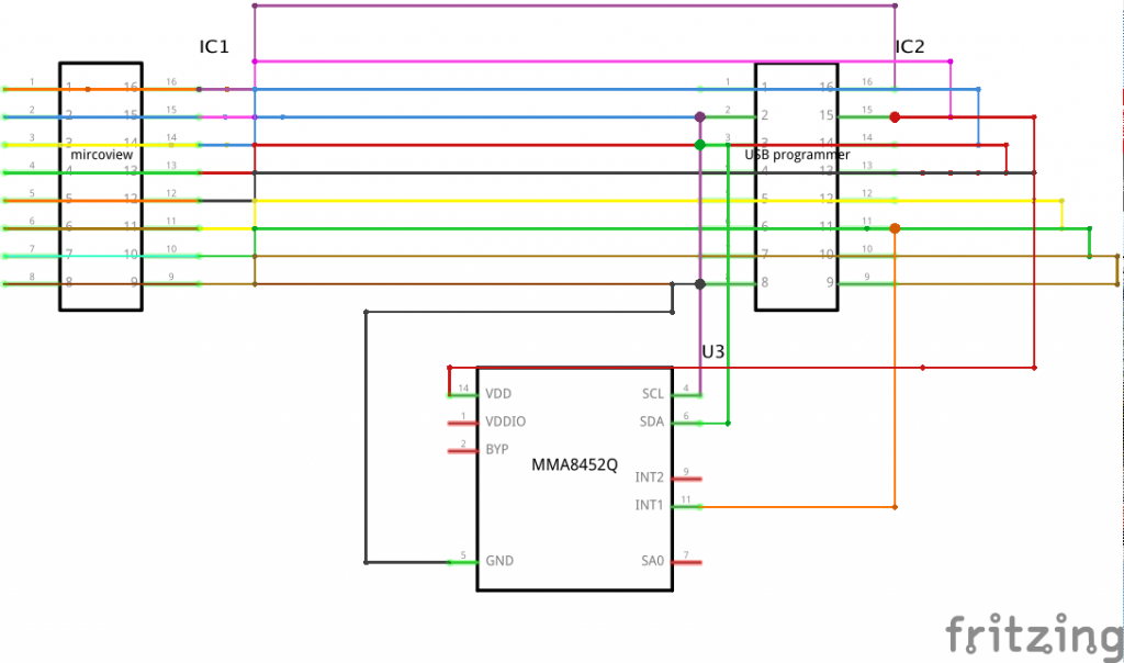
My first step was to draw some sketches of what I wanted my watch to look like. Next, I downloaded Autodesk Fusion, which is a CAD or Computer -Aided Design software. This is what I used to design my watch base. Then, I took all the necessary measurements to allow the watch to fit on my wrist and hold the microview and USB programmer properly. I used a calliper to measure the dimensions of my wrist, the microview screen, and the USB programmer. I made sure to leave some extra room for accelerometer, battery, and wires that will go underneath. After  I completely finished designing the watch base, I had it 3D printed, I soldered the accelerometer and buttons to the USB programmer, and I made a velcro bracket to adjust the fit.

The most challenging part was designing a that would allow me to insert both the microview and the USB programmer. That is why I designed it so that the microview is inserted from the top of the watch and the USB programmer comes in from the bottom.

The skills I have obtained from completing this milestone was is designing projects using CAD and using a calliper.

Documentation

Here are my Fritzing schematics, CAD screenshots, GitHub code, and Bill of Materials.

Second Milestone

My second milestone was connecting the accelerometer to the microview and using it to play a pong game.

The example code  provided for me was for a pong game that used a potentiometer. However, I decided to challenge myself by using an accelerometer instead. An accelerometer is a device that measures acceleration, and  acceleration is the rate of change of velocity of an object. This is an important aspect of my project because it allowed me to tilt the microview up and down to move the paddles in the game, and I’m able to implement the accelerometer into other features.

I accomplished this milestone by first connecting the accelerometer to the microview with jumper wires. Then, I downloaded a library that gave me a demo for how to print the values on the accelerometer when it’s tilted. Once that worked, I moved on to developing the pong code to work with the accelerometer. This has been by far the most difficult part of my project because I had to learn how and what to change in the program that would make the game work with an accelerometer. I resolved one of the issues by using the Arduino map function to change the range of values on the y-axis of the accelerometer into the range of values on the y-axis of the microview screen. This is what allowed the paddle to move accurately on the screen.

Two major things I learned were an understanding of accelerometers and coding in Arduino. My next milestone is to learn how to switch between each program and to figure how I’m going to make the physical watch.


First Milestone

My first milestone was programming a clock on the microview.

Assembling the smartwatch is the easiest part my project. Most of the work comes in programming the smartwatch. This is an important aspect of my project because it tests that the main part of my project works and that I know the protocol to follow when I’m uploading new features.

This milestone involved installing the FTDI driver and Arduino Software, understanding how to download and implement the Microview Libraries, and comprehending the code that was provided for me. I learned that the  FTDI driver is used to control the USB programmer, which connects the microview to my computer to program it. Some other information I obtained from completing this milestone was an understanding of libraries and programming with Arduino. A library is a precompiled collection of codes that you can reuse in other programs. I used the time library I downloaded from GitHub to program the clock. Although I didn’t write the code myself, it gave me a starting point to learn about how I can program the rest of the features on the microview.


My next milestone would be to completely finish programming the microview.

Starter Project

For my starter project, I built a universal remote control called the “ TV-B-Gone”, that functions as a power button. Its components consist of a pair of batteries, resistors, and capacitors, a button, five transistors, an oscillator, a microcontroller, an indicator LED, and four Infrared LEDs.

Here is how it works:

First, the button is pressed to turn off the controller and released to reset it. As soon at it resets, the indicator LED continuously blinks to indicate that the microcontroller is functioning properly. The resistor sets the brightness of the indicator LED by limiting the current going through it. The capacitors store the charge needed to power the controller when it’s turned on. Next, the oscillator makes sure the microcontroller is functioning at the correct speed. The microcontroller is what stores all the code for the controller and turns the IR LEDs on and off. Because the microcontroller cannot directly power the IR LEDs, the four transistors assistant with that. The IR LEDs send infrared pulses to the television that represent binary codes. The television translates the codes into commands. For my controller, the command is to turn the television on and off.

I learned a lot throughout this project. For starters, I learned how to solder, which is tons of fun. Most of my learning experience came from overcoming challenges. Assembling the controller was relatively easy compared to understanding my project. Because I never worked with a circuit before, I had to thoroughly research each component, their functions, and their role in my controller. Despite the work, I enjoy learning new information I can implement into future projects.

Leave a Comment

Start typing and press Enter to search

Bluestamp Engineering