Smart Arm Bracer
The Smart Arm Bracer, which is a wearable technology product that can give you all sorts of information about the environment around you.
Engineer
Meghna K.
Area of Interest
Computer Science and Computer Engineering
School
BASIS Independent Silicon Valley
Grade
Rising Sophomore
Final Milestone
BlueStamp was a thrilling new experience as everything I did here was completely new to me; I had never worked on a project like this before, or even coded in Arduino. Over the course of the last six weeks, I learned so much more about engineering than I thought I would be able to learn in such a short amount of time. I learned so many useful skills, from learning how to solder, to coding, properly making connections with wires, and finally coming up with a project plan and integrating the entire thing into one gadget. This project was challenging and I faced many obstacles along the way, but with each one, I learned more. Getting first hand experience with building and tinkering with engineering was really exciting to me and it made me really interested in pursuing engineering more than ever. I want to tinker with this in the future and improve upon my project even more.
 Important Links:
BOM
Schematic
Code

Third Milestone
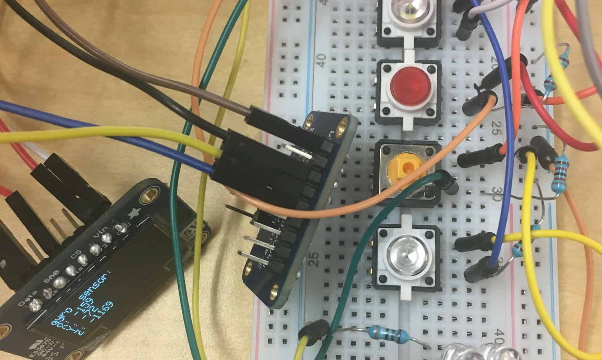
For my third milestone I added four buttons on my project as well as three sensors. The third sensor I added was an accelerometer, magnetometer, gyro, and temp sensor. It is the Adafruit LSMDS0, and is all of those in one. Because of this new sensor, I added another button for it. I also hooked up my OLED to this project. When I press a button, the information from the sensors will now show up on the OLED. This is very important as it is the part that the view will see their data. I edited my code to incorporate these changes, so the data will no longer print on the Serial Monitor.
 While hooking up the OLED and the new sensor, I didn’t have any major problems as they were similar to what I had done previously in this project. However, when I was trying to hook up another button, it wasn’t working properly. After looking into the problem for a while, I realized that the resistor I used wasn’t the right one, so I need to replace it with one of the correct value. I was running out of room on my board to place everything, so I decided that instead of sticking my sensors to the breadboard directly, I would use male to female wires so that they would hang out, and there was more room for my buttons. I also drew up a schematic for my project,so that when I transfer it onto my leather bracer and have a reference for that transition.

Second Milestone
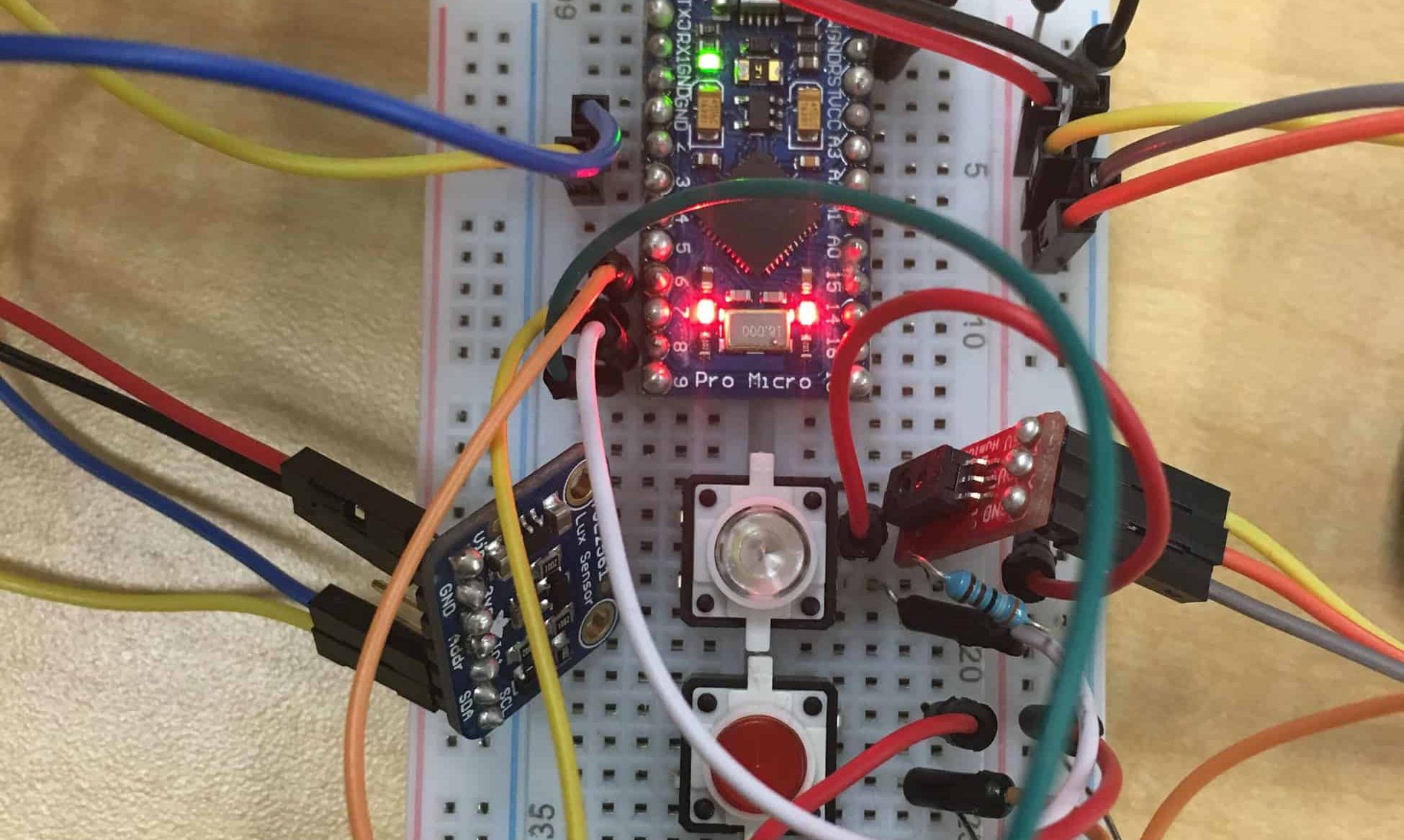
For my second milestone, I added three buttons to my project. The white button controls the the lights, which can be used as a flashlight. When you press the white button, the light will turn on. When you press the button again, it will turn off. I used standard white LEDs for the flashlight, and simple resistors. It was a little confusing at first, since it was my first time using LEDs and resistors, but I soon understood it. The red button controls the light sensor so when pressed down it will show the readings from the lux sensor. The yellow button controls the humidity sensor so when you press down on the button,it will show the readings from the sensor. The humidity sensor I am using is from Sparkfun and it is able to check the humidity of the surrounding area.
 I had a couple of problems while trying to hook everything up. The first was that I had some faulty wires, so I had to check all of them to make sure they all worked. After that happened, I was able to successfully receive data from my humidity sensor. Once I got that plugged in, the micro USB plug-in broke on my Sparkfun Pro Micro, and I had to replace it with another one. Unfortunately, my GPS wasn’t hooking up very well, so I decided to work on the buttons components of my project. My white button and my red button worked pretty well, but for some reason, my green button didn’t work. After a lot of debugging, and checking everything, I finally realized that the green button was broken, and had to replace it with another button, which was yellow.

First Milestone
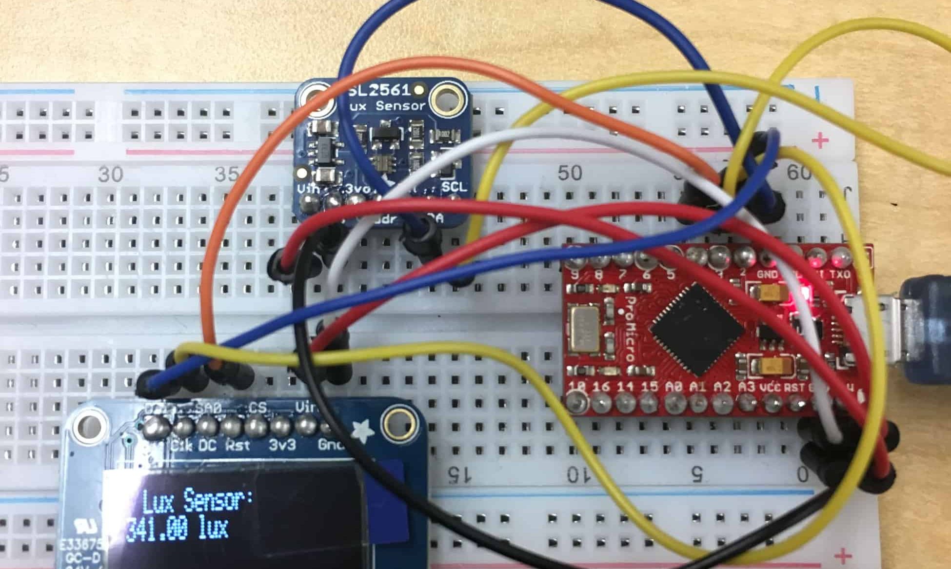
I decided to film my first milestone when i got my oled display screen and my lux sensor up and running. The lux sensor I am using for this project is the TSL2561 luminosity sensor, sold by Adafruit. It can be used to precisely measure the luminosity around it, and has a range of 0.1 to 40,000 lux! It uses very little current, and uses an I2C interface. The OLED display I used was also made by Adafruit. It is a small 1.3” 126×64 graphic display, but can be used to show a variety of cool patterns and text. I connected both of these sensors on a breadboard, and hooked them up to my Sparkfun Pro Micro chip, which was connected to my computer through a Micro-USB cable. The Pro Micro is coded through Arduino, a type of coding program that I had not previously used before. It was difficult to learn an entirely new language, but after a few instructional videos, tinkering around with it and some LEDs, and memorizing the syntax, I was able to grasp the basics enough to code properly.
 After that, I started to hook up my lux sensor to the pro micro. At first, it was a little tricky as the guide used diagrams of the Arduino Uno, which had pins that I didn’t know where to find. It was easier once I looked through the guide to find where the SDA and SCL were located on my Pro Micro. However after doing so, it still wasn’t working. I then realized that the connection was poor. To fix this, I soldered on pins, and then it started to work. The lux sensor data was now showing up on the computer! I decided to also hook the OLED up, because in the future, I want it to show the readings of my sensors. Learning from my previous difficulty with connections, I decided to solder pins onto the OLED as well. Once I put all the wires where they were supposed to be, I ran my example code, and the screen lit up with designs. Unfortunately, right after that, the port I was using to upload code disappeared. Without selecting the right port, it was impossible to upload code. I spent a lot of time trying to figure out what was wrong, and why the option of my port disappeared. Following a long debug, I figured out that my Pro Micro was bricked. To fix this, I needed to reset the board. Once I did this, it started to work and I could upload code again! From there, I wanted it to display simple text, like it would if I made it display the light sensor data. I had the OLED display the text, “Lux Sensor: “. In future, I would like to get it to show the data from the lux sensor, as well as hook up the remaining sensors.

Starter Project
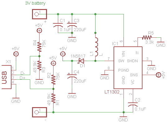
My Starter Project is the Minty Boost 3.0. The Minty Boost is a portable charger for almost any device. With just two double AA batteries, it can provide up to 75% charge on an iPhone, and is compatible with many other devices, such as a camera, or an MP3 player. This project taught me how to solder, as I had to solder four capacitors, five resistors, a diode and an inductor, as well as an 8-pin socket and a USB jack. In this project, I learned a lot about how a circuit works, and the function of each part in the circuit. The resistors add resistance to the electricity, and control the flow of current. The capacitors store the charge, and the diode ensures that current only flows in one direction. The inductor is used by the DC/DC converter chip to store and convert power from low voltages to high. The IC socket protects the 5V boost converter chip. The USB jack is where the charging cable can be plugged in.
 The most important thing that I learned was to double check if the component is polarized or not. In my case, I forgot that the diode is polarized, which means that they need to be placed in a specific way. However, I placed in the opposite way, and had to go through the painstaking process of desoldering it. After I finished, when I connected it to my phone, it still wasn’t working. After checking it multiple times, and using the multimeter, I learned that the wire that connected the batteries to the circuit weren’t connected properly. I attempted to desolder the wires so they could be properly connected, but accidentally scraped off the connections in the process. Because of this, the wires were unable to connect properly, so I redid the project. Using my experience and previous project as reference, it turned out much better. I tested it, and it now successfully can charge my iPhone whenever I need it.


