Engineer

Meghna G

Area of Interest

Mechanical Engineering/ Industrial Design

Touch Screen Tic-Tac-Toe

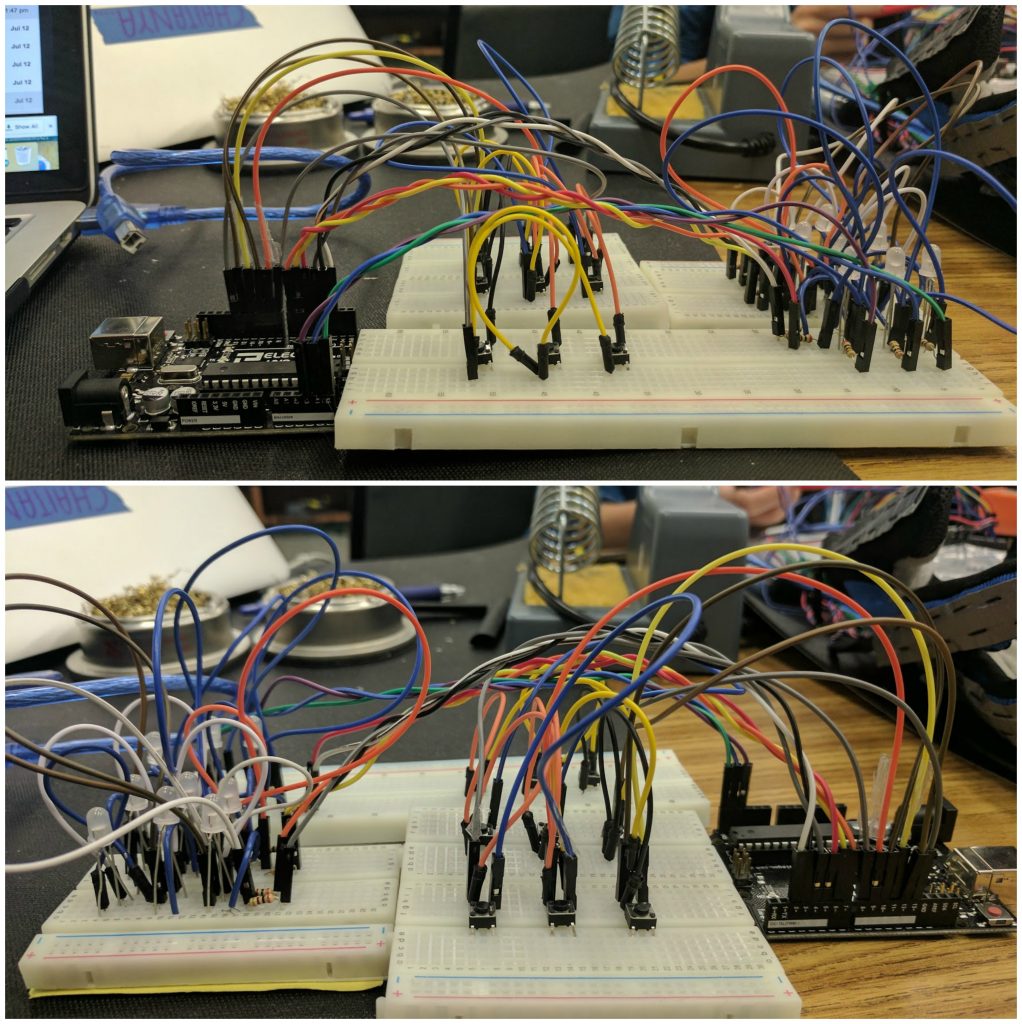
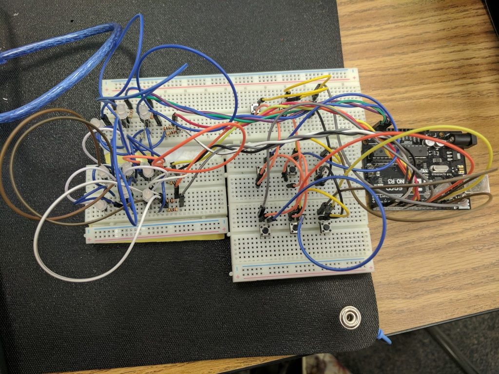
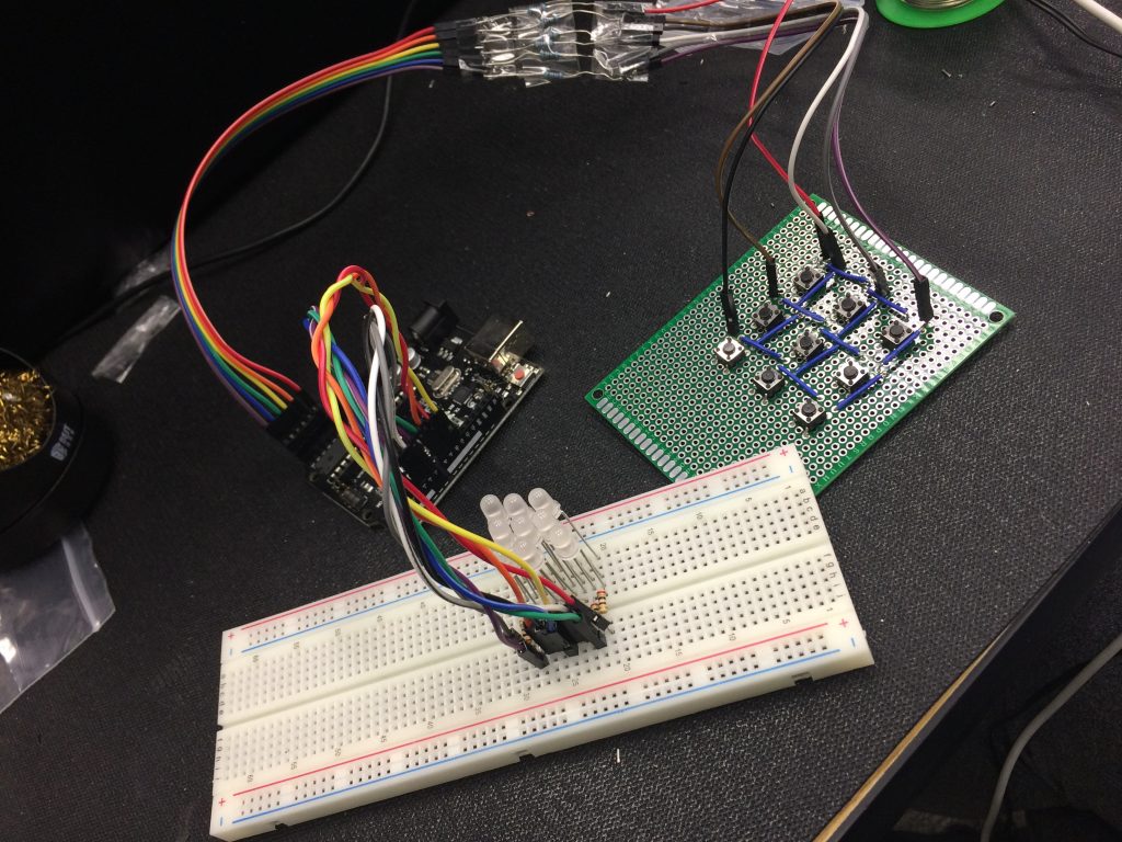
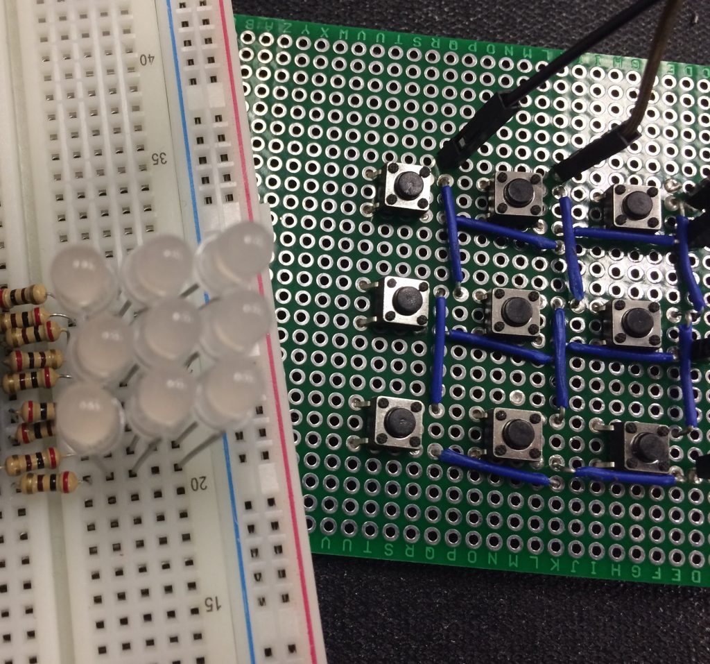
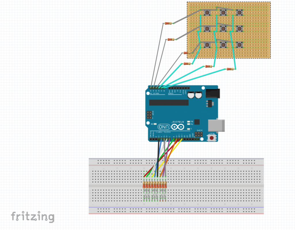
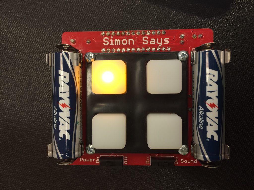
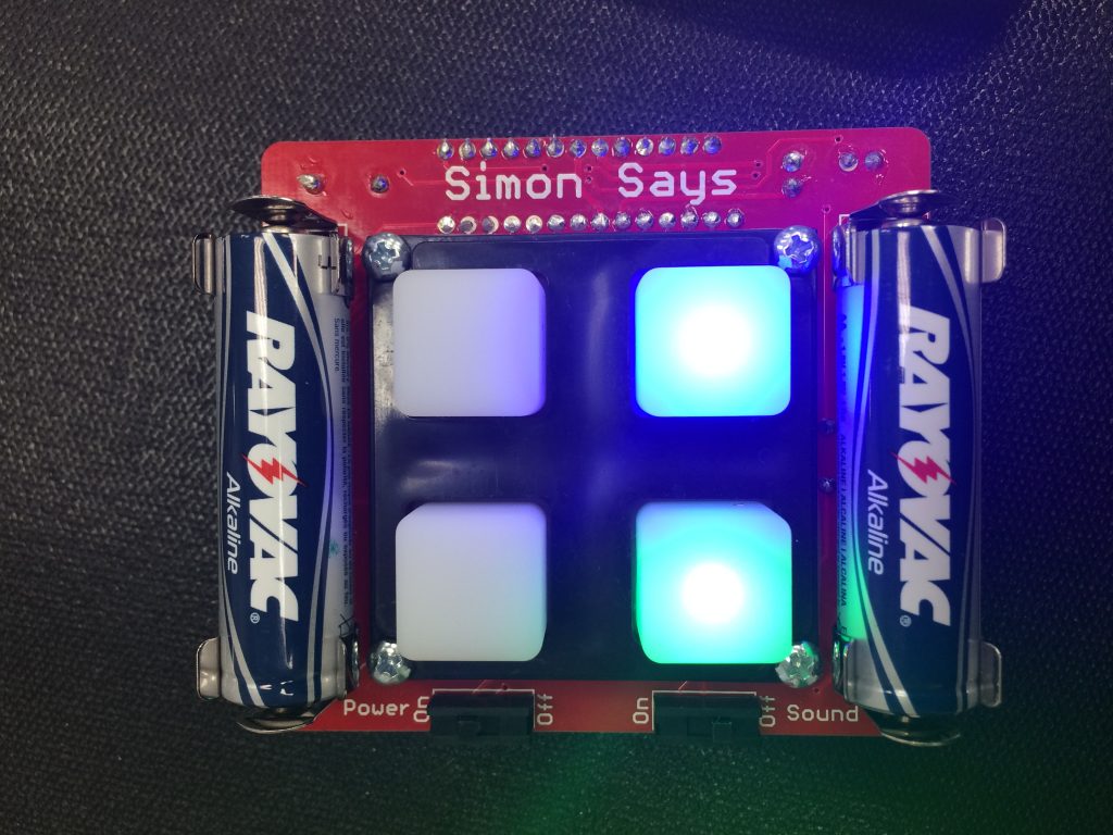
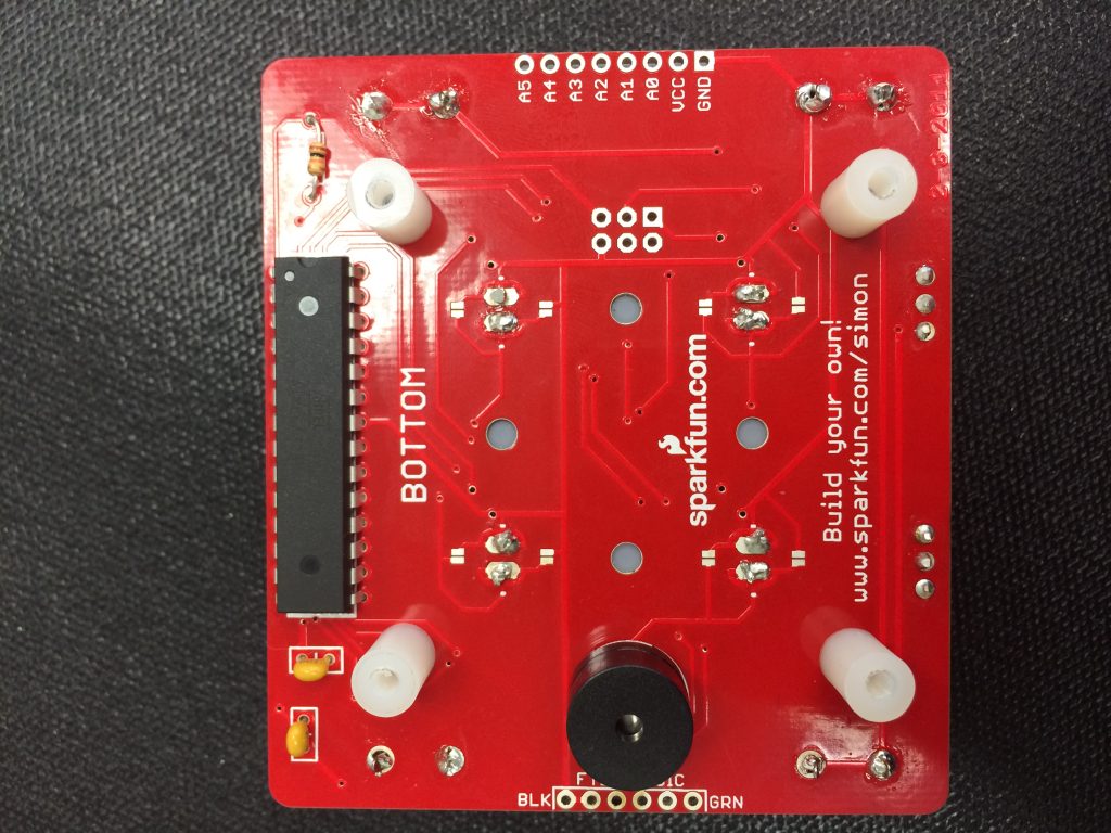
Hi! I’m Meghna a rising sophomore at Saratoga High School. My starter project was a Simon Says Game, and my main project is a touchscreen tic-tac-toe game. The tic-tac-toe game consists of a 3×3 matrix of bi-colored LEDs as part of the display, a button-pad, and an Arduino Uno.

School

Saratoga High School

Grade

Incoming Sophomore

Reflection

During BlueStamp, I learned a great deal about engineering and myself. I came to BlueStamp hoping to learn more about all the different types of engineering because I had previously only had experience with mechanical engineering. I also gained the ability of being to research and solve problems on my own without having to constantly ask for help and just be given the answer. I was able to use multiple pages of google and solve the problems on my own instead of being spoon fed.

Another major thing I learned about myself, was what type of engineering I enjoyed. My project involved mainly coding and electrical engineering, and by the end of the 6 weeks, it was becoming clear to me that although I didn’t hate software, I definitely enjoyed mechanical and electrical much more. The ability to deal with an actual physical product and be able to clearly see the problem was much more enjoyable for me. Altogether, BlueStamp taught me many useful skills, and allowed me to learn more about myself. These are things that I will carry with me throughout school.

Bill of Materials 

Final Code 

Final Milestone – Final Prototype Game

Most Updated Version of the Code and Hardware

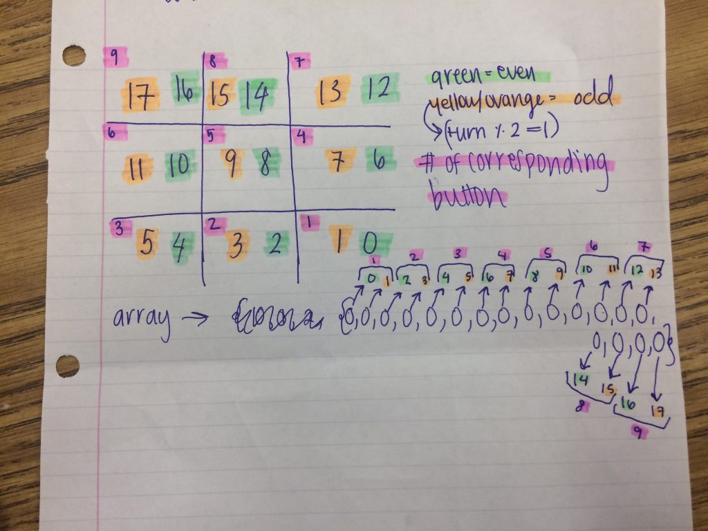
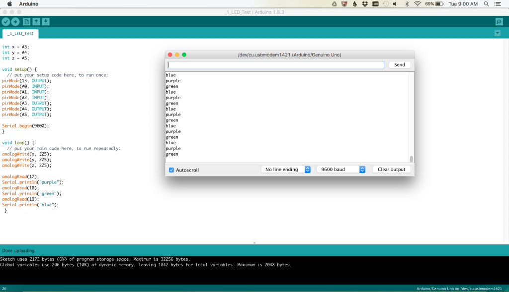
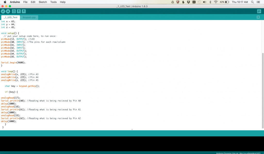
My 3rd milestone involve updated and correcting my code from my last milestone. I added in win conditions, so that the Arduino would be able to recognize if someone has won the game and I found a way to have multiple LEDs “light up at the same time”. For the lighting the LEDs, I created an array with 18 values. All of them were set to 0. Because an array is 0-indexed, the name of the values only went up to 17. I then corresponded each button to 2 of the values. For example, Button Number 3 would correspond to the zero’s that were labeled 4 and 5. The 4 would correspond to the LED being lit green, and the 5 would turn the same LED yellow. (See the diagram on the left).

Using this, I added in the turns once again. I set turn equal to 0 in setup, and then added a ++ to it every time a button is pressed. I then said that if the %(mod/remainder) of the number divided 2 is equal to 1, then the LED should light up green. This essentially means that if the number of the turn is odd, then the LED will be green, and if it is an even turn, then the LED will be yellow. In order to have the LEDs appear as if they are all lit at the same time, I used the theory of persistence of vision. This is basically the reason that when you blink, the world doesn’t become completely dark, but instead remains exactly the same as when your eyes are open. This is also how animation works. Every time a button was pressed, it would turn the value from 0 to 1. This array would then cycle through really quickly, and would light an LED for any value that was 1. This created the illusion that all the LEDs were lit up at once when in reality, they were going on and off so quickly it was unnoticeable.

The win conditions were fairly easy to add after this. There are 8 possible win conditions in a game of tic tac toe, 1 for each column, 1 for each row, and 2 diagonals. When programming these in, I also had to take in account the fact that there are 2 different colors, and each color has these 8 conditions, so in total, there were 16 conditions. The logic behind the win conditions was to basically check which values are equal to 1. For example if buttons 1, 4, and 7 were all pressed by green, then you check to see if in the array the values 0, 6, and 12 were all 1 instead of 0. If this is true, then all the LEDs would change to the winning color.

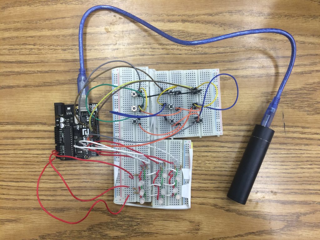
Milestone 2- Syncing the Buttons with the LEDs

Most Updated Version of the Code and Hardware

My second milestone was syncing the buttons with the LEDs. Before doing any coding, I was having a lot of trouble with the connections between not only the buttons, but also the LEDs. Because of the way they had both been designed, it would be extremely difficult to code them. I decided to redo both the button pad and LED Matrix. I used a solder-less breadboard for both. Previously there were certain wires that were already connected to each other without a button having to be pressed, so to fix this, I spread out each row of buttons throughout 3 connected breadboards. The buttons were placed across the intersection of each board. I then proceeded to use male-to-male jumper wires to connect the rows and columns together and to the Arduino.

The main problem with the LED matrix was the that all of the leads were in line. In order for it to work properly, the yellow-anodes, the green-anodes, and the common cathodes must be in separate rows. I bent the leads of each LED and put the short/yellow anodes in one row, the long/green anodes in another line, and the common cathodes in the last line. I once again used jumper wires to connect each one to each other and then to the Arduino.

The last main problem that I faced was where each of the buttons/LEDs were connected to the Arduino. In the original design, the buttons were supposed to be connected to the analog pins, and the LEDs would be connected to the digital pins, and more specifically the anodes to the PWM pins. The reason for the PWM pins was for fading effects, so it wasn’t something necessary for the function of the game. Because the buttons wouldn’t work when connected to the analog pins, I made the decision to connect them to the digital pins 13-8. The cathodes of the LEDs were plugged into the analog pins A5-A3, and the anodes were connected to the digital pins 7-2.

The coding was by far the most confusing part of this game yet. The code that was given by the instructable didn’t work, so I had to write my own code. I started out with just testing the connection between the buttons and the Arduino. There is a screenshot attached below. The first time I did it, I had the words ‘purple’, ‘green’, and ‘blue’ print on the serial monitor, but I soon realized that these words would print even if the connection between the buttons and the Arduino was not happening. I decided to then have the serial monitor print was values the pins were receiving. (The changed code is also attached.) After getting these trials to successfully work, I started to try and program only 1 button and 1 LED. This was fairly easy, so I moved to 2 buttons and 1 LED. Button #1 would make the LED green and button #2 would make the LED yellow. After this worked, I began to try and sync each button with an LED. I did a lot of research on how to do RowColumn Scanning and coding and LED Matrix and the various ways of coding bi-colored LED. Here is the website that showed me how to code what I needed. After the baseline code for the keypad and rows/columns, the rest was mainly copy/pasting the code for each button. In order to add turns, I added the integer turn and set its value to 0. I then made it incrementally increase by 1 every time a button was pressed. If the remainder of the turn number divided by 2 was 1, then I knew it was an odd turn and yellow would show when the button was pressed. If it was even then green would appear when the button was pressed.

Here is the link to the final code

Milestone 1-Building the LED Matrix and Touch Pad

My first milestone was building the LED matrix and Touch Pad. The LED Matrix is really simple. It is 9 bi-colored LEDs, yellow and green, 9 resistors, and 9 jumper wires. Each of the LEDs has 3 leads, 2 anodes and 1 common cathode. The longer anode is for the color green and the shorter anode is for yellow. The LEDs are arranged in a 3×3 array, all facing the same direction. All of the leads for each row are aligned so that in each row, there is one jumper cable per green anodes, yellow anodes, and common cathodes. The jumper wires, male to male, are then attached to specific pins on the Arduino UNO; Common Cathodes → Pin 4, 7, and 8; Yellow Anodes → Pin 3, 5, and 6; Green Anodes → 9, 10, and 11

The touch pad was much more complicated. The original idea was to have 6 wires that crossed each over each other essentially creating 3 rows and 3 columns. At each intersection of the wires there would be a small piece of tape/insulation that would stop the wires from touching. If someone were to put their finger on top of the intersection, theoretically, their finger would conduct electricity and complete the circuit. After spending 2 and a half days trying to make this idea work, I decided to switch to something totally different. Currently I am using 4-pin push buttons. The buttons have 4 pins on the underside that when connected to wires can connect any 2 wires together. I used 9 of these buttons and smaller insulated wires to create my “touch pad”, and after only half a day, they worked. I soldered these wires and buttons into a strip board. Afterwards, I soldered in 6 jumper wires, one for each row and one for each column. These 6 jumper wires were then connected to pins 14-19 on the Arduino.

Starter Project- Simon Says Game

My Starter Project is a Simon Says Game. This game consists of 6 main components, 2 batteries, 4 buttons with touch sensors under them, 2 slide switches, 4 LEDs, 1 micro-controller, and 1 buzzer. All of these parts are mounted onto a PCB or Printed Circuit Board that is designed for this specific game.
The function of this game is quite simple. When the game begins, one of the 4 LEDs flashes. The player must then press the same button that was flashed. This goes on continuously, with the pattern getting longer each turn. Each time a button is pressed, the touch sensor underneath sends a signal back to the micro-controller. Each of the buttons has a different sound that corresponds with it. When a button is pressed, a signal is sent to the micro-controller, which then sends a signal to the buzzer to make the specific sound. When a wrong button is pressed, a signal is sent to the micro-controller, and the game is stopped.
Overall, this project was really fun and taught me a lot of new skills. Because this was a soldering kit, I learned how to solder, but additionally I learned the function of many new components that I was unaware of. For example I learned that a micro-controller acts like a mini computer that is programmable with a set amount of memory. I also learned that LED stands for Light Emitting Diode, and that a PCB is a Printed Circuit Board. I hope to be able to use everything I learned in my main project as well!

Leave a Comment

Start typing and press Enter to search

Bluestamp Engineering