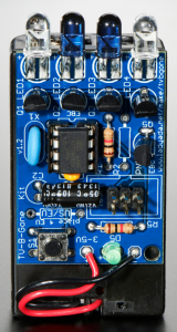
Infrared Remote Jammer
The Infrared Remote Jammer is a device that prevents the user of the regular remote from changing the channel on the tv. It mimics the IR LEDs that are in the remote for the TV.
Engineer
Matthew Bergman
Area of Interest
Cyber Security
School
Riverdale Country School
Grade
Rising 10th grader
Milestone
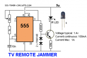
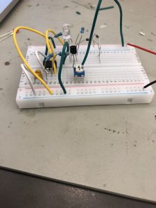
My first milestone is the completion of the prototype version of my project, the IR Remote Jammer. The prototype was built on a breadboard and I went through 3 different designs to build this successful circuit. The project uses a 555 timer to know when to send out the waves of infrared light to the tv, preventing the user of the tv from changing the channel. The original design and the second design used 2 diodes which was preventing the IR LED from firing, so they were replaced by a resistor. The finished prototype utilizes a bc547 transistor, resistors ranging from 5.6 ohms to 12k ohms, a 10nf capacitor, and a 10k variable resistor. The whole circuit is powered by a 9 volt battery.
The challenges that I faced was that I was unable to figure out why it was not working with the 2 diodes, so when it was not working it stumped not only myself but also the instructors. It took the help of the internet and the instructors to help me troubleshoot, but in the end it was fixed and now it works as it should. The project really helped to learn how breadboards and circuit works so now i have a good understanding of it all. The project also helped me to learn about wiring because there was a lot of problems with wiring.
TV-B-Gone