DMX Controlled Light
The project is to create an LED moving light that is controlled using the DMX protocol. The light will be able to rotate and tilt to cover the entire stage using two servos and change the color of the wash to any color in the RGB spectrum.
Engineer
Matthew H
Area of Interest
Mechanical Engineering
School
University High School
Grade
Rising Junior
Reflection after the Program
For my second year at BlueStamp I wanted to make something more complicated than I did last year. I originally expected for my project to entail making a rather simple circuit using a breadboard and an Arduino with a DMX shield. But I ended up having to essentially create my own Arduino with a more accurate clock than the normal one and my own DMX connector as well as modify the Arduino hardware serial library. I also assumed that I would spend more time working on the frame as my interest still lies within mechanical engineering and not trying to decipher DMX signal, troubleshooting problems with the Arduino itself, or creating a power regulator circuit to power the ICs. This year I had to do more troubleshooting and learned how to program with Arduino as well as extended my knowledge of electrical engineering that I started last year.
Main Project
Final Milestone
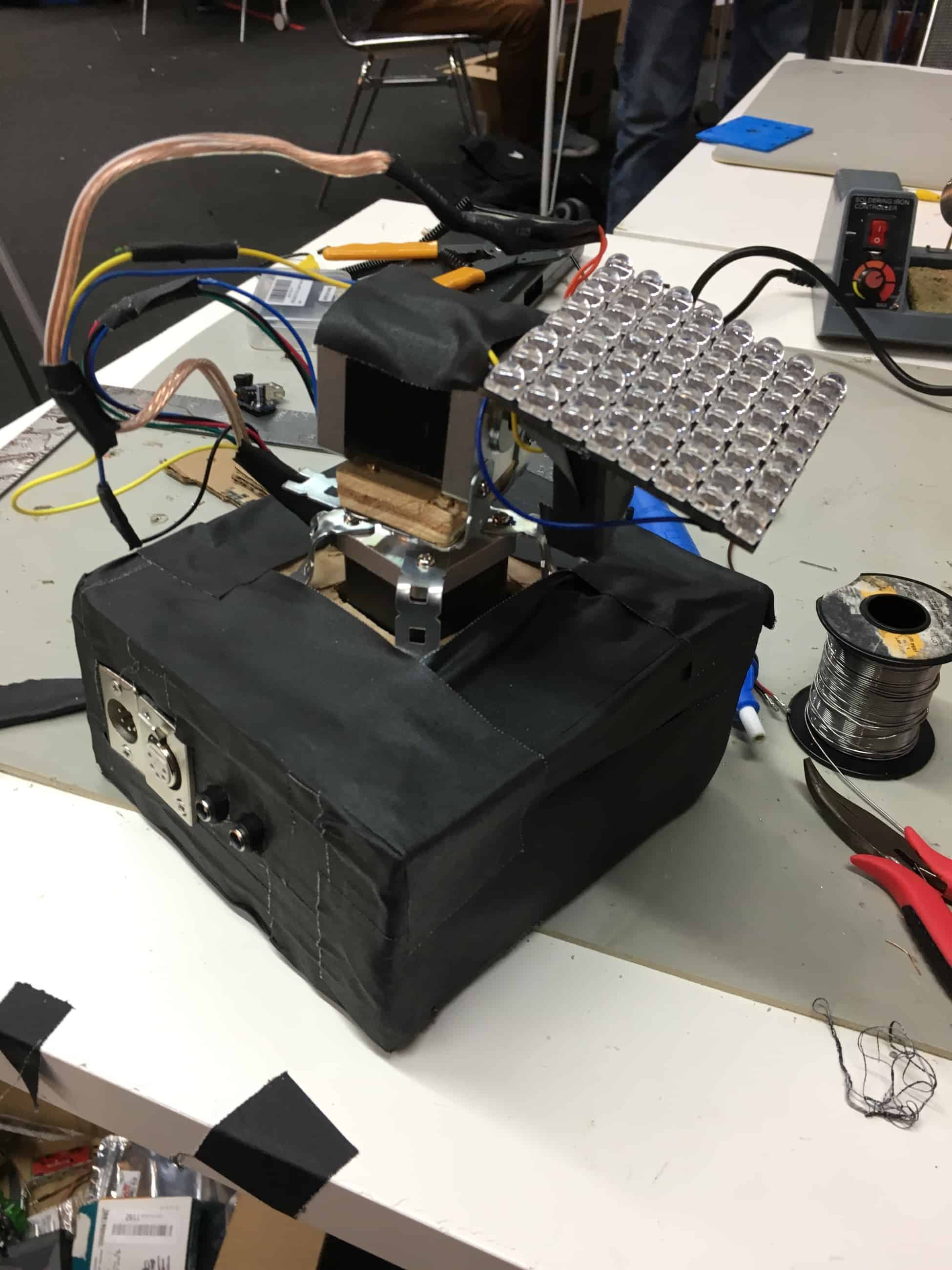
For my third and final milestone I built an enclosure for my light. I originally wanted to build one similar to the lights I use at school but that turned out to not work due to torque limitations of the motor. So I sized things down to attach things closer to the center of the motor. This also didn’t work but that was caused by the current limit on the motor drivers set to low for the motors. Because of this change I needed to increase the current output of the power supply. To prevent from burning out more motor drivers I added heatsinks to the H-bridges and voltage regulators as well as a fan blowing onto them. I mounted the four connectors to one side of the case and drilled a hole in the top for the wires to come out. I left two sides open to allow for the fan to have an exhaust and for ease of access. I covered all of the wood with black gaff tape to prevent it from splintering.
I had many problems getting things to work. The first few were caused by small shorts or cracks in the solder due to the tight space constraints. Another one was caused by the fact that I hadn’t had both power supplies on the same ground causing for the data to be garbled. At the end one of the motor drivers wouldn’t connect properly and kept losing power which caused for the other driver to lose information and not step properly. While doing some testing I accidentally plugged my 12 volt power supply to the LEDs, which are rated for only 5 volts and this fried all of them.
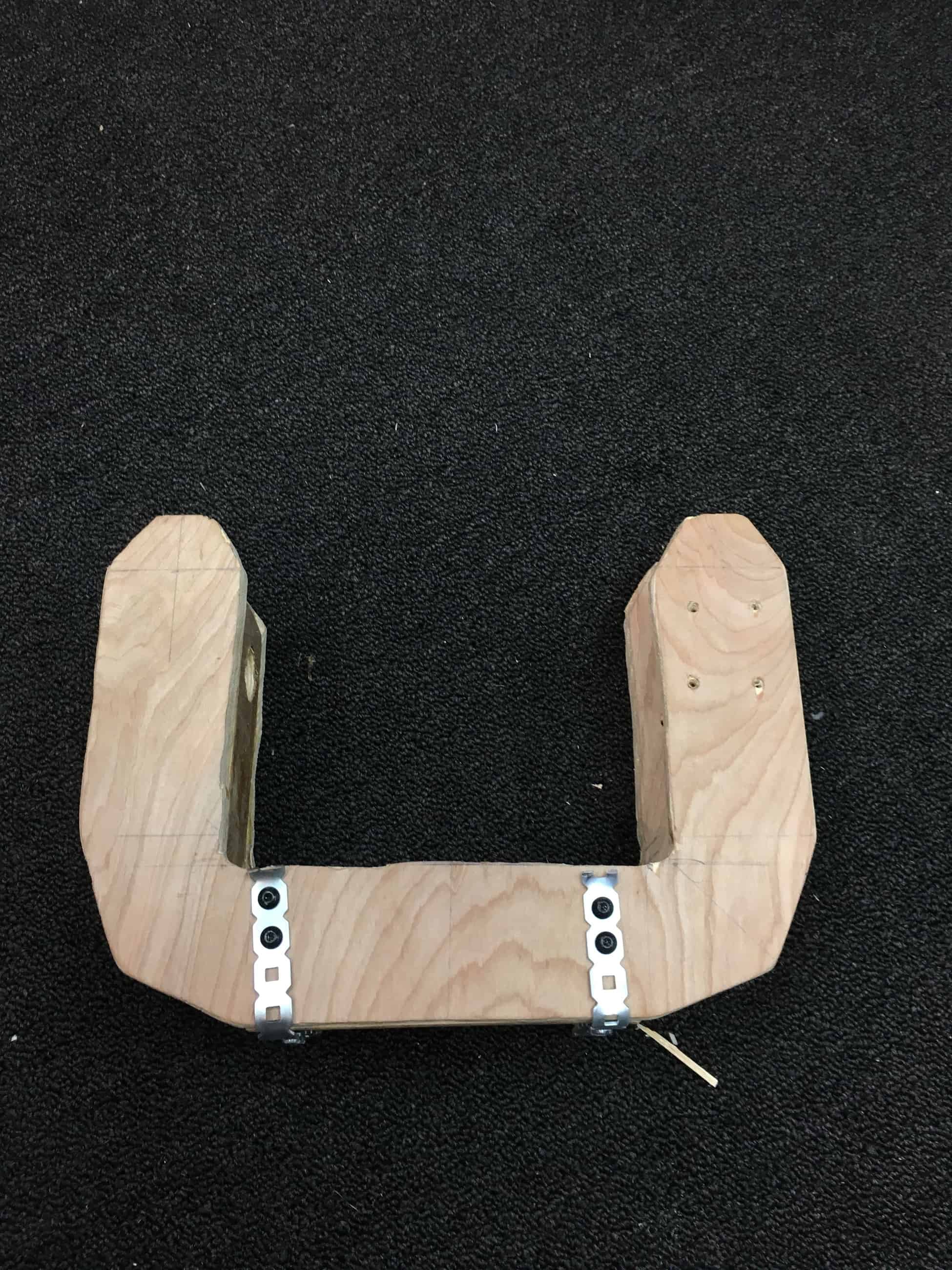
Original Frame Design
Final Light Design
Second Milestone
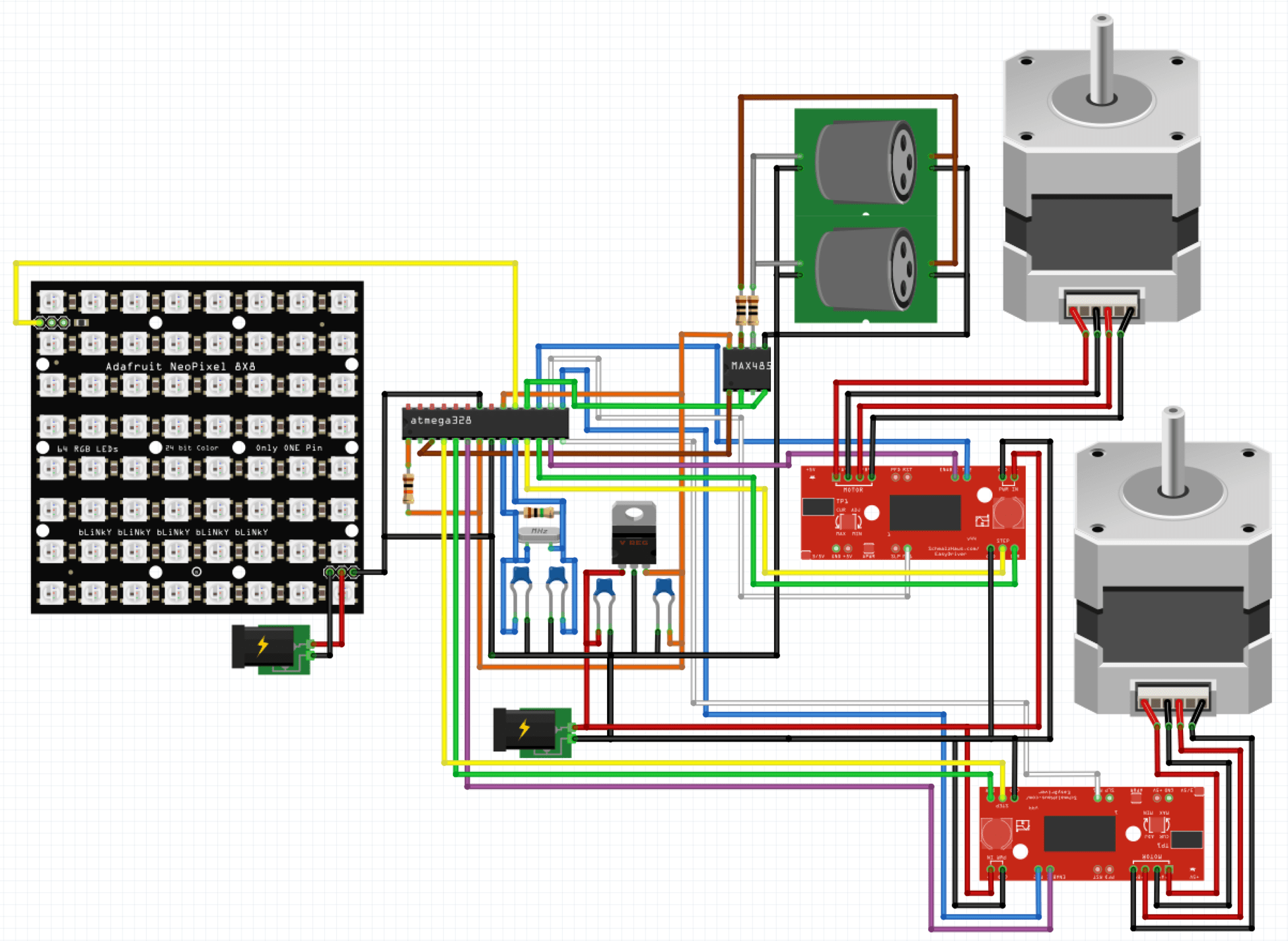
The second milestone of my main project is to get the electronics and control software of my light working. There are four main parts of the circuit: the ATMega, the motor control, the LEDs, and the DMX connector. The ATMega is connected to a 5 volt regulator and a 16 MHz crystal resonator, which is connected to ground using two decoupling capacitors. The two bipolar stepper motors are controlled by one EasyDriver each. The EasyDrivers are connected to five pins digital pins and one ground each. The four stepper motors wires are connected in pairs to the coil contacts on the EasyDrivers. The motor drivers take their power from a 12 volts external power supply, also connected to that line is a fan used to cool the motor drivers and LEDs. The LEDs, an 8×8 matrix of RGBW Neopixels with a warm white, are connected to another digital pin on the Arduino, as well as a ground pin. The LEDs are controlled using the Adafruit Neopixel library, which handles the PWM. The LEDs are powered by their own 5 volt 4 amp powersupply while the rest of the circuit is powered off of one 12 volt 1 amp powersupply with the motor drivers and fan using straight 12 volts and the ATMega and MAX 485 on their own regulated 5 volt rail from the 12 volt powersupply. To make the circuit more permanent I soldered all of the components to a solderboard. I decided to have the pan motor on channel 1, the tilt motor on channel 2, red on channel 3, green on channel 4, blue on channel 5, and white on channel 6. I did this because it is similar to the lights that I am familiar working with at my high school.
I had lots of timing problems due to the issues with the Arduino’s clock. To solve the problem created by the inaccurate ceramic oscillator that regulates the ATMega328, I moved the ATMega to a breadboard and added a 16 MHz crystal oscillator which improved the reliability a lot. To power the ATMega I needed use regulated 5 volts as to not damage the chip so I added a 5 volt regulator. Because of the way the Arduino deals with hardware serial I needed to use a modified version of the hardware serial library from Max Pierson. The modified library removes an interrupt included in the original library. Even with the improved oscillator and hardware serial library I needed to add a delay of 32 ms after the LEDs run to prevent them from flickering. When I originally connected my motor drivers, neither of them was working properly, they were moving very slowly and not at the right increments. This was caused by the drivers being stuck in the microstep states, the pan motor was in 1/2 step, and the tilt motor was in 1/16 step. To fix this I connected the microstep control pins to the ATMega’s digital pins and set them to output low, disabling the microstep modes.
DMX LED Moving Light Schematic
Link to code: https://github.com/ThePandaJedi/DMX-LED-Moving-Light/tree/master
First Milestone
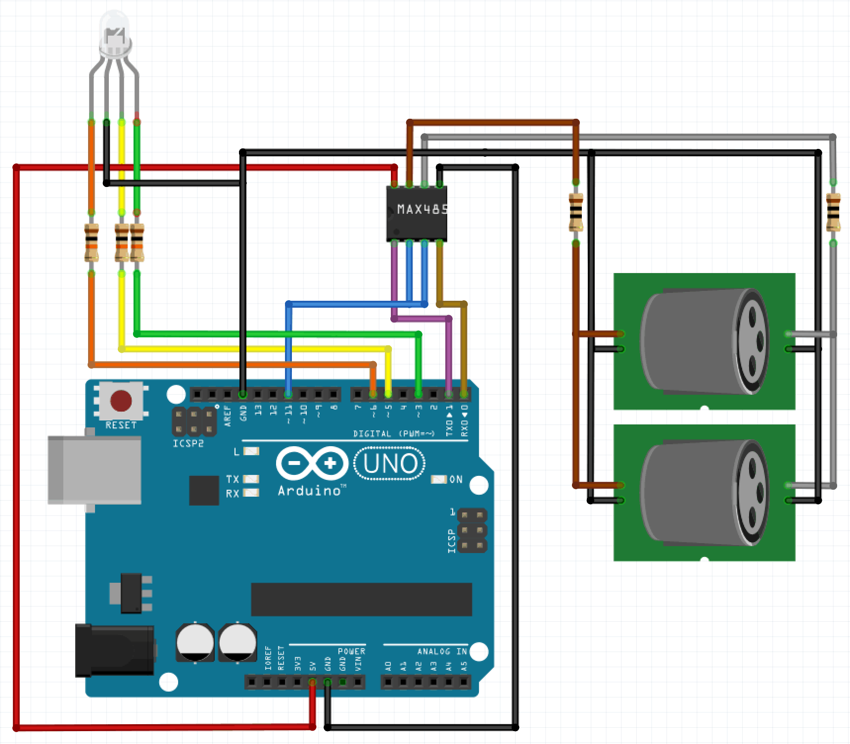
The first milestone of my main project, a DMX controller LED moving light for theater, is to get the Arduino to read the DMX signal from the DMX controller and change the color of an RGB LED based on the values of three DMX channels. DMX is sent over the RS 485 communication standard. RS 485 uses two wires that are opposite voltages of each other to improve signal integrity and transmission speed. The signal is read by the MAX485 microcontroller which is a transceiver of the RS 485 signal. The MAX485 is connected to the data plus and data minus pins on the male XLR 5 pin jack. Because most DMX devices can be used in a daisy chain I added a female XLR 5 pin jack which is connected directly to the male jack. To add signal isolation I added two 10 Ω resistors between the data plus and data minus pins on the XLR jacks and the data inputs on the MAX 485. DMX uses a long idle period to start a data packet which begins with a zero channel. Each channel begins with a low start bit followed by eight data bits and ends with two high stop bits. DMX operates at a bitrate of 250kbps, each bit taking 4 microseconds. To interpret the DMX signal I am using the DMX library from Toni Merino.
DMX Connector Schematic
Link to code: https://github.com/ThePandaJedi/DMX-RGB-LED
Starter Project: DiceKit

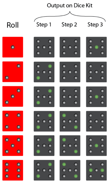
Schematic
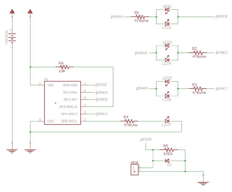
Kit, Images, and Schematic are from SpikenzieLabs.


