Binary Clock

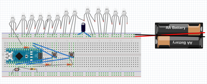
The binary clock uses an Arduino Nano to control the 16 LEDs that make up the clock.  The first two columns are the hours, the next two are minutes, and the last column changes every 10 seconds.  It is the same as a regular clock except you read it in binary.

Name

Lawrence J.

Area of Interest

Mechanical and Electrical Engineering

School

Homestead High School

Grade

Incoming Junior

Reflection

At Bluestamp, I learned a lot about how circuits work and engineering in general.  At school, everything I have done is exclusively with software.  My school, Homestead High School, did not have an engineering class until the 2017-2018 school year.  As a result, I have only taken computer science courses, which is just programming.  At Bluestamp, I was able to learn how to work with hardware and integrate software and hardware.  After learning skills like soldering, making engineering drawings, and how to connect components to and arduino among other things, I managed to make a project that works in six weeks.  I know that I still have a lot to learn, but I have progressed a lot in the past six weeks, probably more than I would at any other program.  At Bluestamp, they encourage independents and figuring out the solution to your own problems.  The instructors ask you to Google things before you ask them, which made me learn much more than I would have had they just given me an answer.  I know that I will definitely be able to utilize the knowledge I have gained at Bluestamp in many future projects as well.

Showcase Night

Second Milestone

Second Milestone - Integration into case

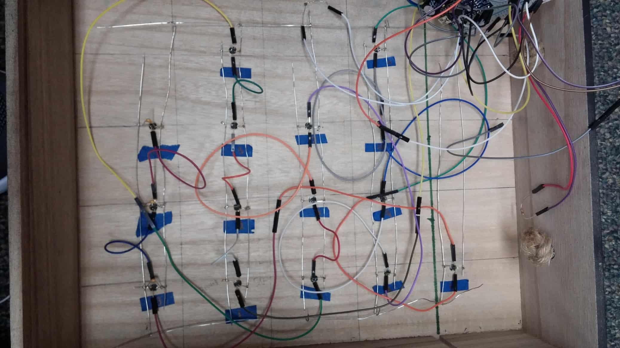
Engineering Diagrams, Drawings, and Schematics

The grid(jumper cables are for input and output)

My second milestone was to get everything from my breadboard integrated into my case.  The biggest challenge was completely rewiring all of the LEDs.  I learned that the all LEDs could be connected through each other through their power and ground, which means that you can connect the power of one LED with the power of another LED.  This means I can plug one LED into the breadboard, which has the power, and run a wire along the whole column of LEDs to power all of them. I have one long wire for the power and one long wire for ground on each column.  In addition, I have one really long wire connecting all of the ground wires and one really long wire connecting all of the power wires.  The whole circuit looks like a grid.  The only wires that are recieving power directly from the breadboard are the two long wires above. The light dependent resistor resides in a small hole above all of the LEDs to accurately measure the light. Some changes I have made is three extra LEDs I added at the right side of the box to symbolize tens of seconds.  The other change I made is spray painting my box black to make the green LEDs stand out more. If I had more time, I would want to modify the binary clock so it can access the internet and change colors based off of the weather.  For example, it if is cold outside, then the color changes to blue.  If it is hot, then the LEDs will turn red.

Bill of Materials

Bill of Materials

First Milestone

First Milestone - Getting the actual clock working

Fritzing Schematic

My first milestone was to finish the actual clock, with the minutes and hours working together with the push buttons.  The hardest part after wiring everything together is the binary encoding.  The binary clock has four columns, with the first one having two LEDs, the second having four LEDs, the third with three LEDs, and the fourth one with four LEDs.  It is read through binary, but instead of reading it in a row, it is read through columns.  The least significant bit is at the bottom while the most siginificant bit is at the top. The binary was coded by calculating the units digit of the minutes and hours.  The units digit was then represented in the second and fourth column, while the tens digit was represented in the first and third column. The push buttons are connected to analog output pins while the LEDs are connected to digital pins on the Arduino.  One push button increases minutes by one and the other increases hours by one.  My clock is in a 12 hour format, so it resets hours back to one if it exceeds 12. My next steps will be to integrate a light dependent resistor into the circuit and customize my box to show the clock as an actual clock.

Starter Project

Starter Project - MintyBoost

My Starter Project is the Minty Boost USB charger.  The Minty Boost is a portable charger that takes two AA batteries and converts the energy into an output of five volts, which is capable of charging most personal devices. The Minty Boost works by taking in the three volts from the batteries, and running it through a diode, which makes it so that the current only flows from the batteries and into the power inductor.  The power inductor stores the power by creating magnetic fields.  As the magnetic fields reach their maximum size, the boost converter chip controls the flow of the current into the inductor.  The boost converter chip opens the circuit as the magnetic fields reach maximum size, releasing all the stored energy.  As the magnetic fields collapse, the current spikes, which results in an increase in voltage.  This creates a ladder graph of voltage, so there are two electrolytic capacitors, along with two ceramic capacitors, that stabilize the voltage into a constant five volts.

Leave a Comment

Start typing and press Enter to search

Bluestamp Engineering