Hi I am Laurel N and I am a rising senior at Castilleja School in Palo Alto, California.
My starter project was a color organ that displays a LED light show in rhythm with sounds in the environment.
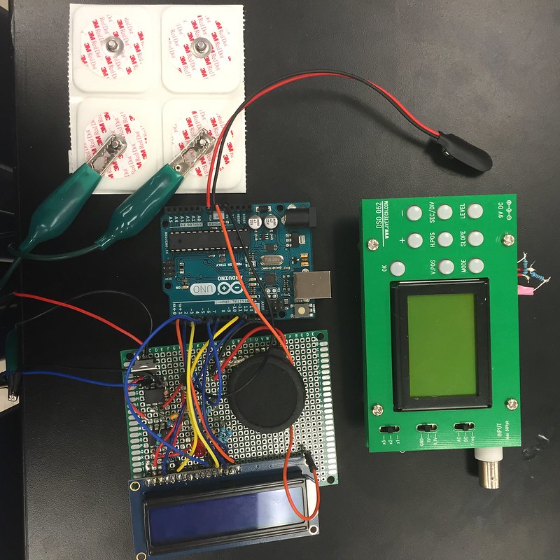
My main project was an EKG on a perf board and an oscilloscope. Read below to learn more about my engineering process!
I had explored various engineering fields in a course at my school but this program allowed me to develop skills in combining electrical engineering and computer science with my field of interest biomedical engineering which is very valuable as I near entering the workforce. With all of the problems I encountered with my projects, I also learned a lot about troubleshooting!
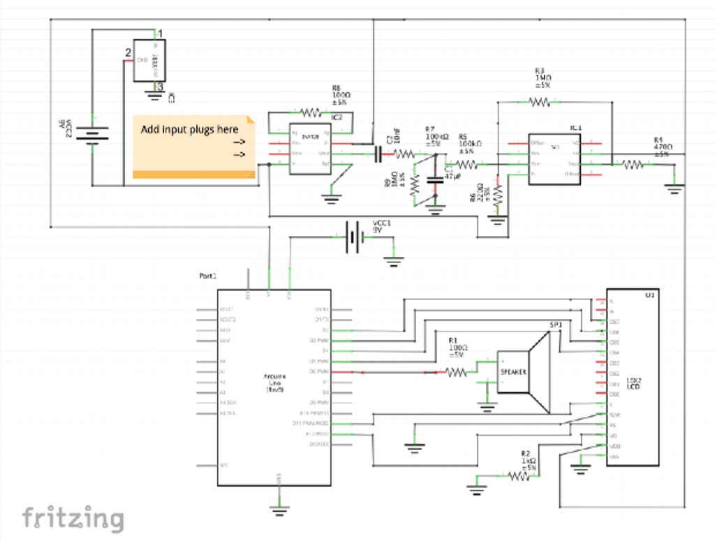
EKG Schematic:
Final Project
Hi everyone! The past three weeks I have worked on assembling an oscilloscope and transferring my EKG from a breadboard to a perf board.
The oscilloscope kit came with a PCB and the appropriate parts. After assembling the oscilloscope, I went to test it using a function generator. The screen first would not light but after adjusting the contrast by turning the potentiometer the graph appeared. Even with this adjustment, the oscilloscope did not recognize any signal. This began the troubleshooting phase of my project. I first examined the schematic and use the multimeter to check all of the connections, later confirming the orientations of the imputed parts. After emailing the manufacturer of the product, it was revealed that PCB board sent was missing parts and the documentation sent with it was not updated. This taught me to evaluate everything given to me with my own knowledge prior to blindly trusting a product’s legitimacy. Currently, I am waiting for a new kit from a different manufacturer to be shipped to me so I can still make a functioning oscilloscope to compliment my EKG.
Meanwhile I began transferring my EKG on the breadboard to a perf board. A perf board allows for the project to be slimmer and more professional. In theory, correctly transferring the components from the breadboard to the perf board would result in a working EKG. Unfortunately my assembled EKG did not recognize any imputed signal. I used the schematic, component data sheets, and a multimeter to test proper connects and everything appeared correct. My instructor told me that she thought it was likely too much solder on various components or disconnected solder on the ground rail. I learned that too much solder could cause resistance which would be detrimental to the function of the circuit. It was also difficult to test whether the ground rail had consistent connections throughout. In the coming weeks I plan to install a new ground rail using a socket so that I can ensure that the connection is consistent and take off some of the solder throughout. If the problem still persists I will consider restarting assembly on a new perf board where I can control solder amounts or transferring the set up to a PCB.
Although I am disappointed that my EKG and oscilloscope are not working currently, my work does not end with this program! I have learned a lot about the engineering process and I am excited to use my acquired troubleshooting skills to get my projects to work! I look forward to sharing my progress in the coming weeks with my instructors, peers, and beyond. Thank you for this amazing learning experience.
Milestone 1
After many days of designing, constructing, tweaking, and testing, I have finally completed my first milestone! My EKG(electrocardiogram) functions properly by recognizing signals created by the patient’s heartbeat and then amplifying and editing them into signals that the Arduino can recognize. The Arduino will read these signals and display the patient’s heartbeat through a blinking LED, beeping buzzer, and a numerical output on the LCD screen.
As I confronted problems with my EKG, I ultimately learned a lot more about about the functions of the specific parts in the circuit. The voltage regulator at the beginning of the circuit has the unique function of producing a negative five volt output(-5V) from a positive nine volt input(9V). When I first tested my EKG, it would not recognize any signals inputed(we tested both with my own heartbeat and a simulated heartbeat from a function generator) and thus constantly outputted a flat line on the buzzer, a consistently lit light, and a “you’re dead” message on the LCD. After studying the schematic provided by “birdyberth”(username of instructables user that provided the instructions to make the EKG) and the datasheets of the components of the circuit I realized that the schematic was labeled incorrectly and that the voltage regulator should be providing a negative voltage instead of a positive one. After making the output voltage negative by switching the ground and output pins of the voltage regulator, my EKG recognized my heartbeat. Although this was an improvement from before, the EKG recognized my heartbeat so irregularly that the machine itself would not be useful in providing a reliable bpm. I deduced that the reason the EKG was not recognizing signals accurately was because the tin foil electrodes I made were not capturing the intensity of the signals. I then tried using professional electrode pads and they were able to capture the heartbeat signals more reliably. With this change, my EKG finally functioned properly!
There are also two ICs(integrated circuits) incorporated into the circuit. The first IC(an instrumentation amplifier) amplifies the heartbeat signal, which then passes through a low-pass filter(composed of capacitors and resistors) that simplifies the signal by filtering for small frequencies within a set range. This signal then passes through the second IC (an operational amplifier) which compares the two voltage levels at its inputs and outputs a high voltage level and a zero voltage level to both the LED and the Arduino. When the LED recognizes the high voltage level it will light up and when it recognizes the zero voltage level it will be unlit. The Arduino also takes in these high and zero voltage levels and outputs them to the speaker and the LCD screen which triggers their appropriate responses visible to the viewer.
One other challenge I faced was that the EKG would only function when the oscilloscope was plugged into a particular pin. I fixed this problem by adding a 1M resistor parallel with the filter to match the resistance the oscilloscope added when plugged in. Up next, making my own oscilloscope!
Milestone One Video

Schematic
Starter Project
My starter project is a color organ. The color organ recognizes sound waves as they hit its microphone and translates them into a dynamic LED display. The color organ consists of twenty-five colored LEDs varying in color from green to yellow to red. The LEDs light up in differing patterns and intensities dependent on the frequencies and amplitudes of the sound waves hitting the microphone. The user can modify the sensitivity and speed of the LED display by turning the dials of the two potentiometers(also referred to as trimmer resistors) in the system. By turning the dials of the potentiometers, the user is changing their resistance which in turn affects the amount of current passing through the circuit. The system itself is powered by a nine volt battery. After an input is recognized by the microphone, it passes through a series of transistors which amplify the input signals. These signals then pass through the first IC(integrated circuit) which sends clock impulses to the second, larger IC(IC2). This IC then sequences these clock impulses and sends them to the four output transistors. Each of the four output transistors controls six LEDs. The center LED is connected directly to an output pin of IC2. The signals of the output transistors are sent to their respective LEDs resulting in the elaborate light display observed by the viewer. Resistors are distributed throughout the circuit to limit the current to the appropriate level for the components involved. This project is a perfect example of relationship between sound and visual effects and while it was fun to make, it is even more exciting to look at!