
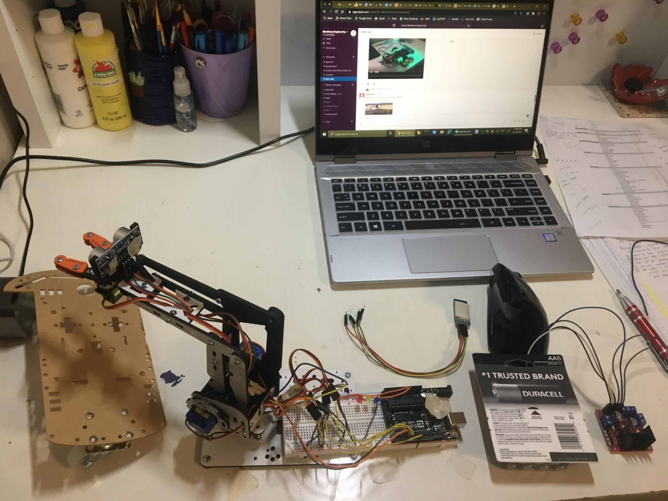
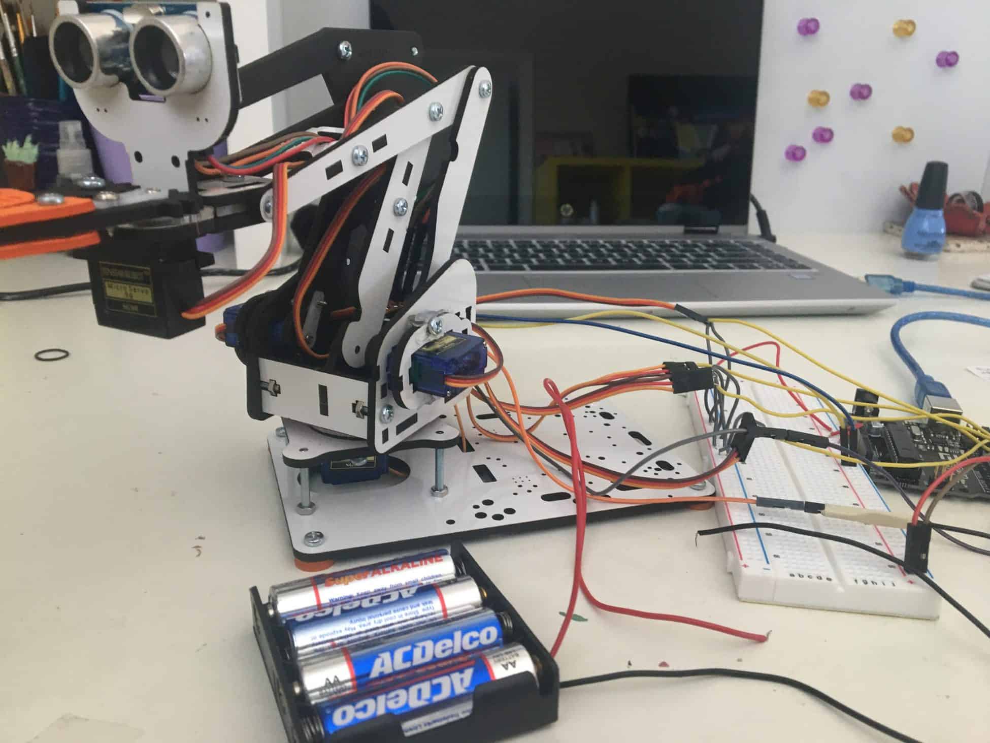
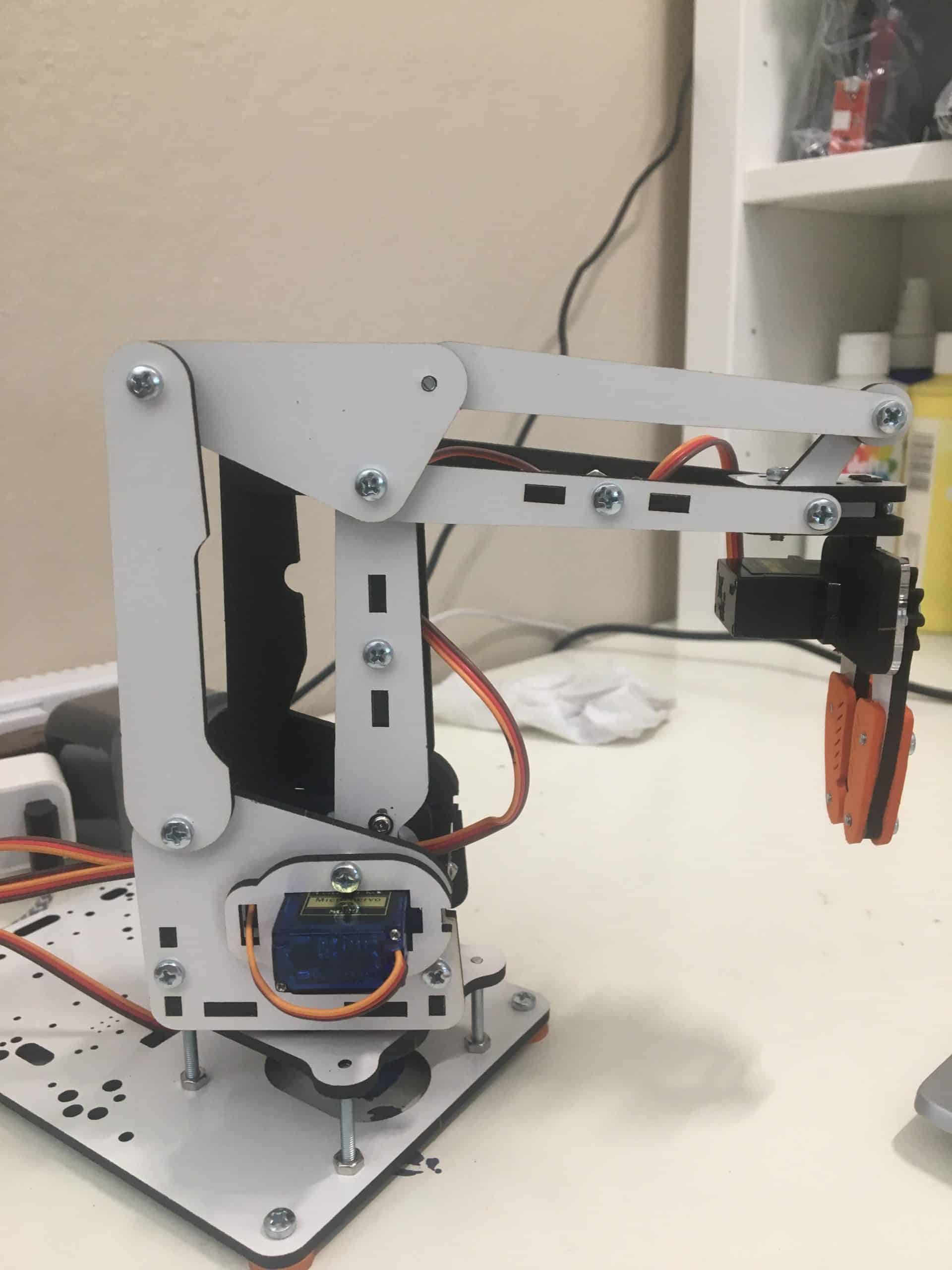
3-Joint Robotic Arm with Claw
The robotic arm is controlled by mircoservos attached to three joints and a claw. My project was centered around building and adding new components to explore different mechanical, electrical, and software features and gain new skills in these fields. The progression of my project through the process of testing, building, and failing, and the development of my knowledge in engineering fields are shown through the three milestones documented while at BlueStamp. My overall experience with building this project was filled with many challenges and successes. I enjoyed going through the design process of having an idea, building, and solving problems. I went into BlueStamp with some background in coding and wanted to explore more mechanical and electrical fields. In the end, I gained an interest and skills in all engineering fields, Looking forward, I hope to apply my engineering skills to real-world problems and work towards finding solutions to issues.
Engineer
Lara V
Area of Interest
Mechanical Engineering
School
Monta Vista High School
Grade
Incoming Sophmore


During the last week of the program, BlueStamp held a Demo Night for us to showcase what we made and present our projects. This is the video from my presentation on my project.
Final Milestone
The final milestone for my project was adding some new features to my overall project. The control system continued to be through the app I customized with MIT App Inventor from the previous milestone. I decided to implement an autonomous mode for my robotic arm, where the arm will find an object and pick it up on its own. This was done using the ultrasonic sensor, which I had used in my previous milestone as a small feature. Here, the ultrasonic sensor is working in the same way, using ultrasound waves to measure the distance of objects around the sensor. The ultrasonic sensor will change a variable to be true if an object s detected within 10 centimeters of the sensor. In order to find an object, I had a method where the arm sweeps 180 degrees on the base servo, allowing it to detect an object from its surroundings. While the arm is rotating, the ultrasonic sensor is also finding the distance of the objects around. When an object is found, the rotating stops and a conditional statement follows with the claw opening up, moving forward, closing up, and moving up to successfully grab the object. This autonomous mode is activated once the user presses the “FIND OBJECT” button in the app.
The app has an additional button called “PARTY LIGHTS” that activates an LED sequence of yellow, blue, and red LEDs. The three LEDs flash is a progressing order to give a nice feature to the robotic arm, and I thought it was a fun idea to have. The LEDs also indicate the mode setting when not in party mode. Yellow indicates manual mode, blue indicated autonomous mode, and red indicates that an object has been found. Having these LEDs is a way to have more components the user can interact with and improve the way the arm functions by making it easier to see what it is doing, as well as providing a pleasant experience.
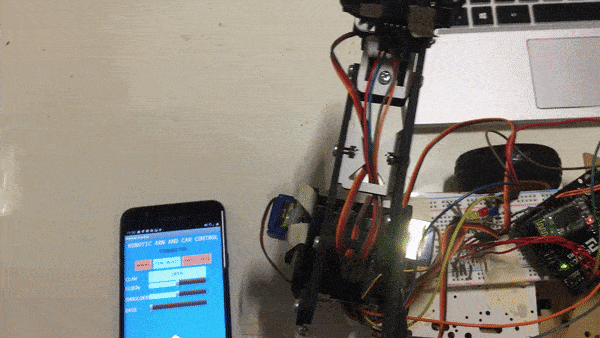
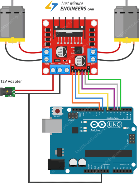
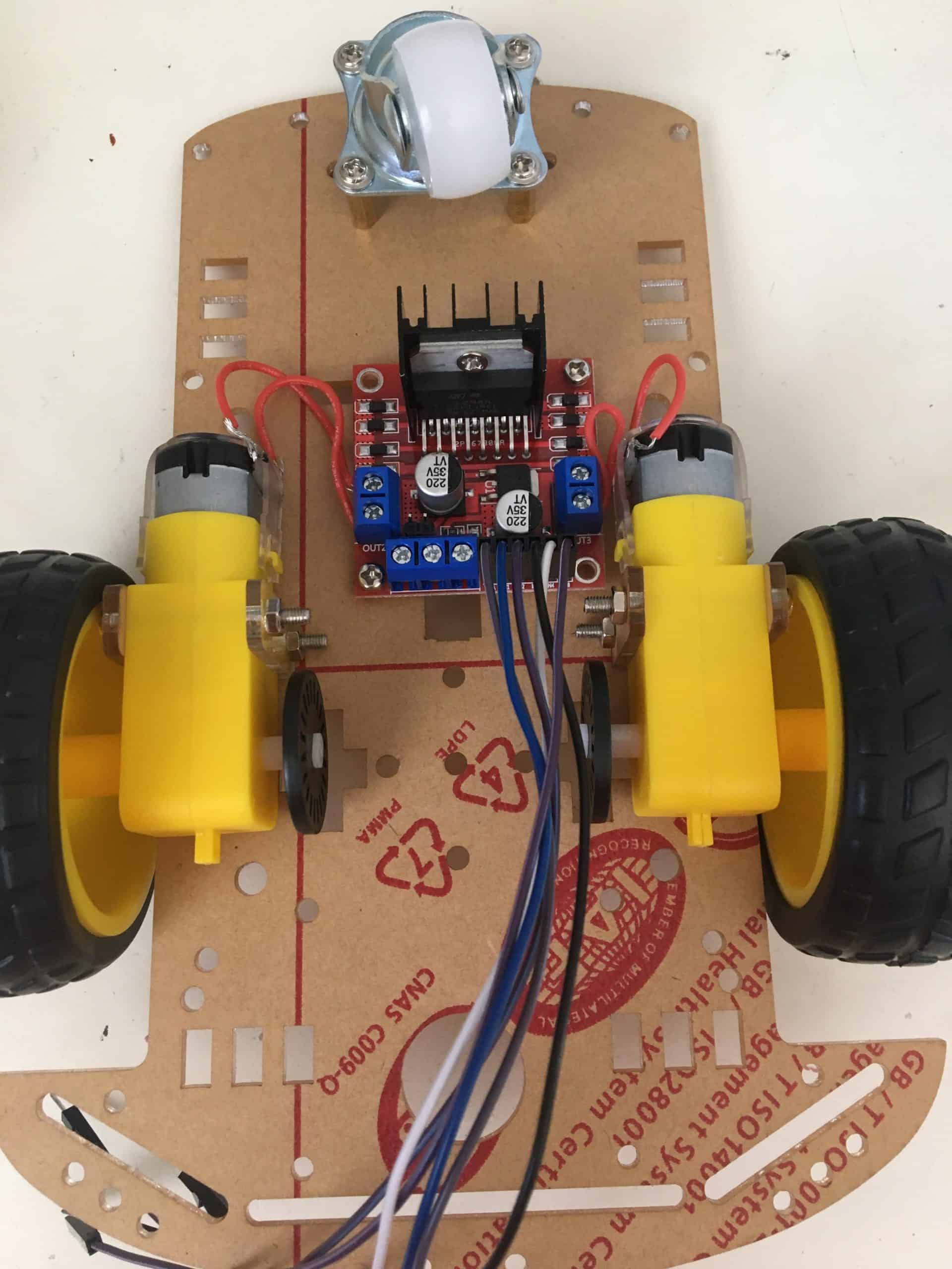
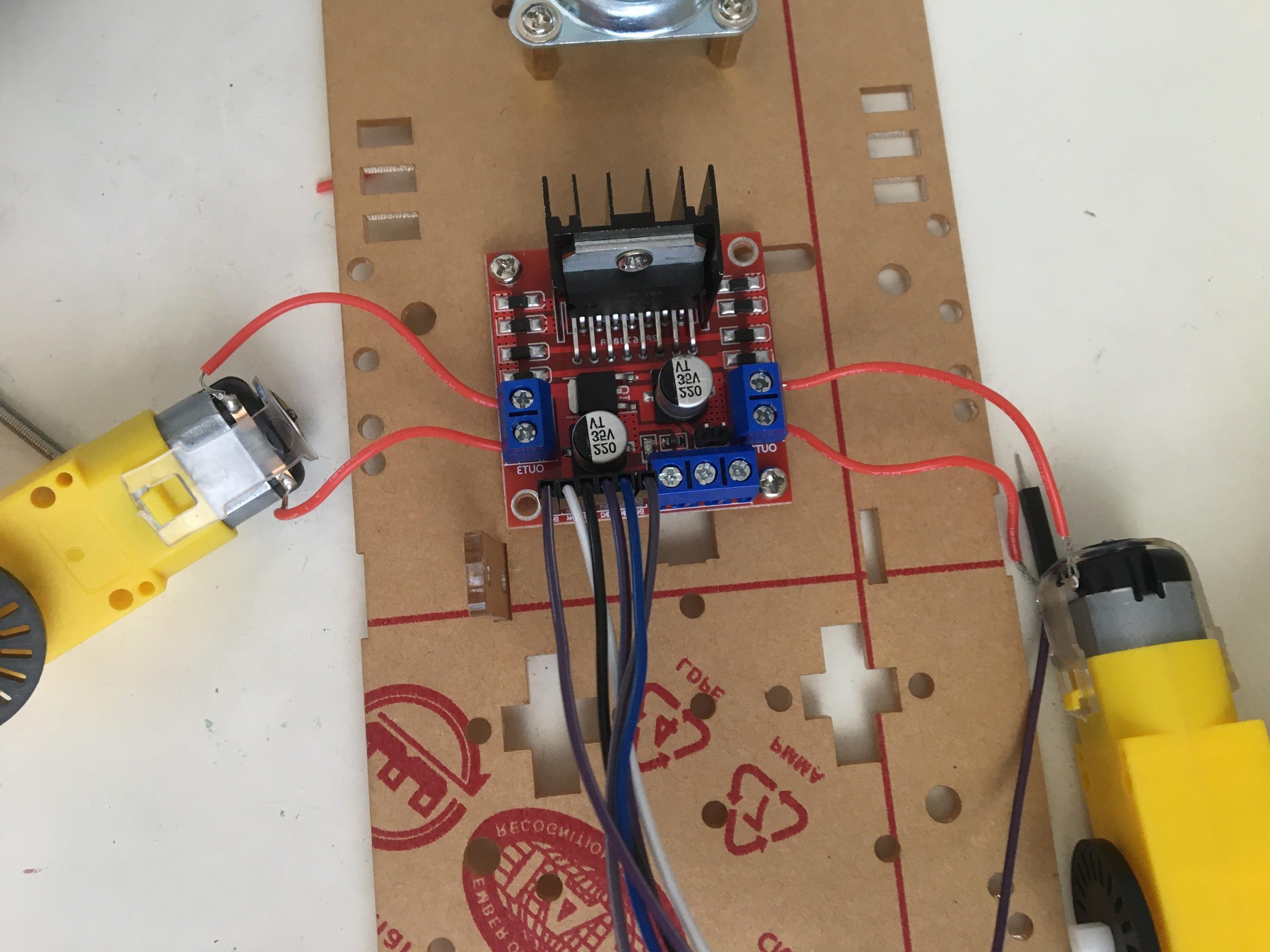
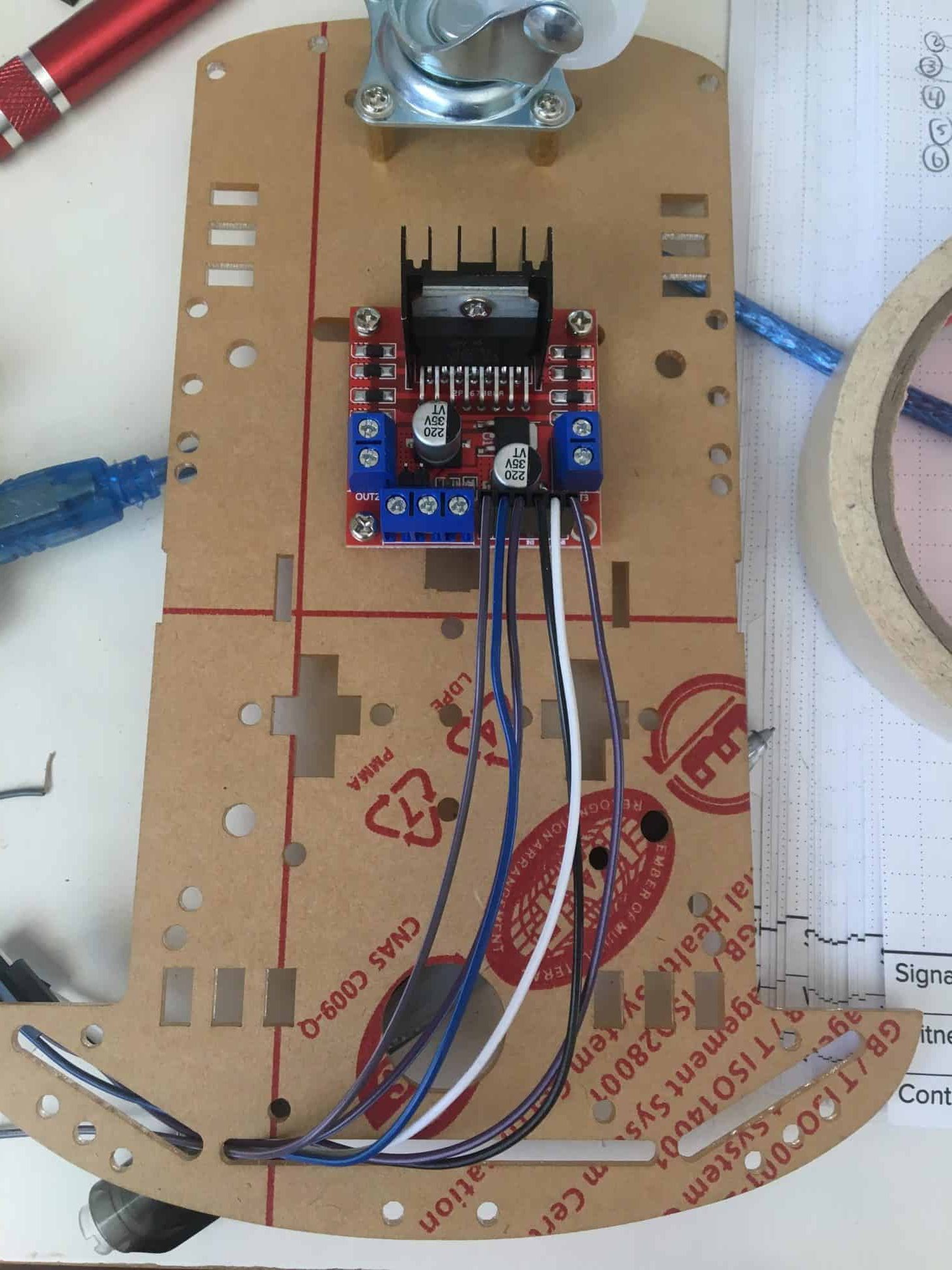
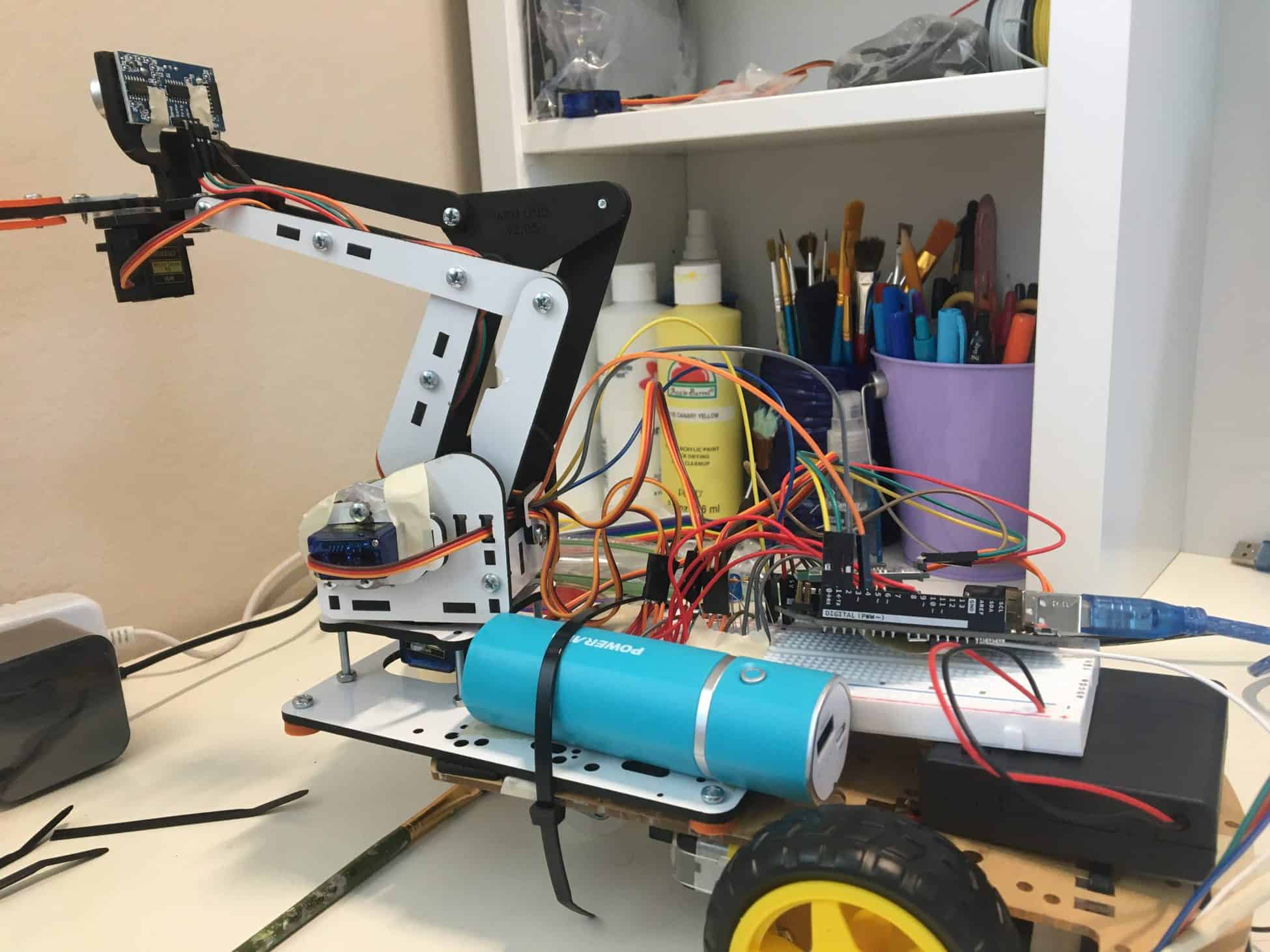
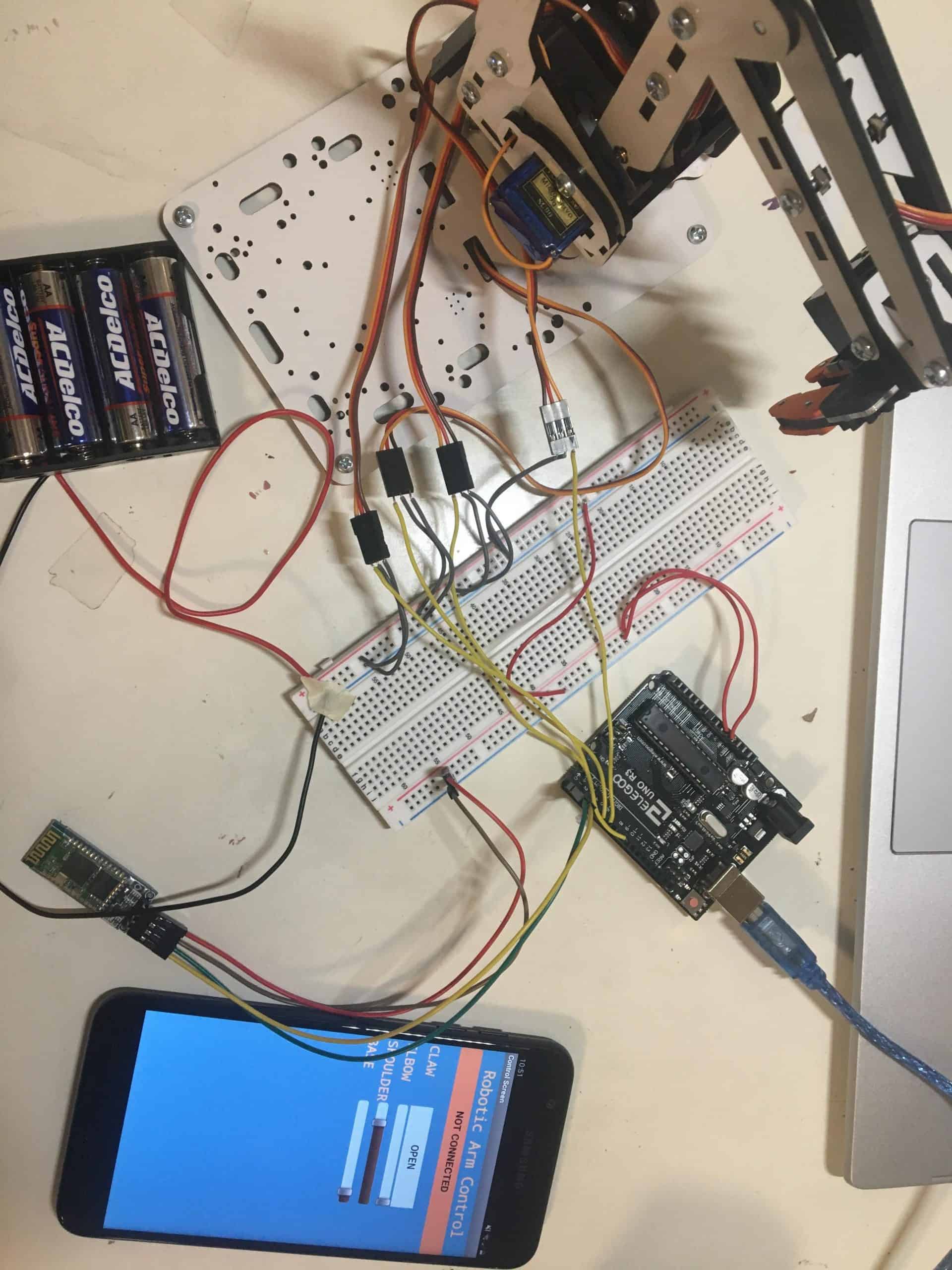
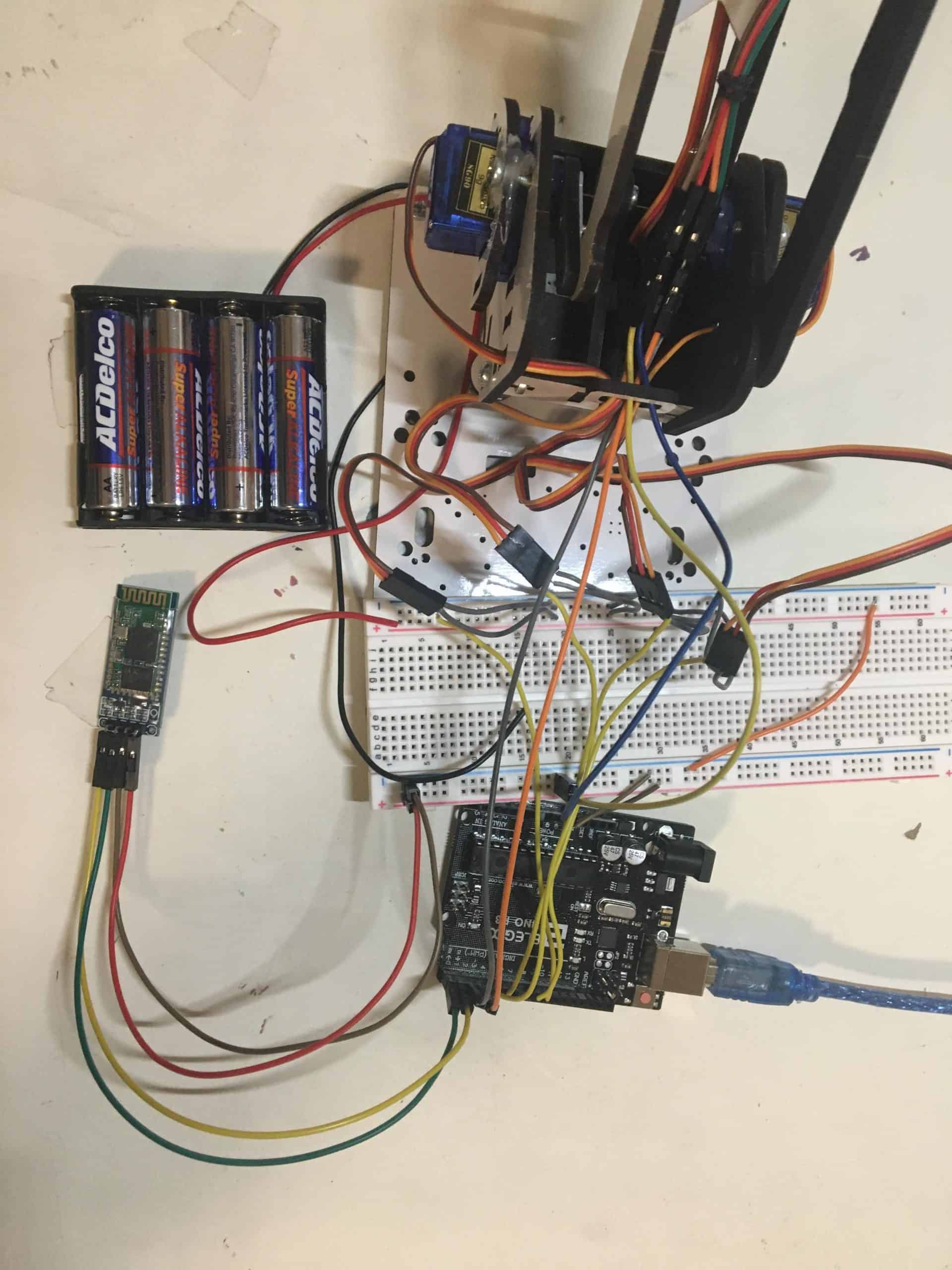
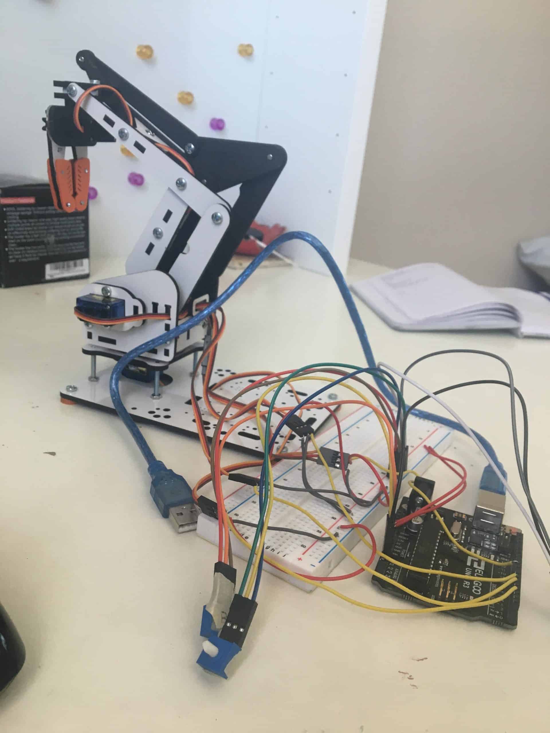
The main modification for this milestone was putting the robotic arm on a car chassis and having a driving feature. The car chassis contained two DC motors that are controlled by a motor driver. I had to learn how to use a solder to solar the wires from the motors to the motor driver. Using the motor driver, the code I used can send signals to the motors to change the rotation direction and speed of the motors, allowing four degrees of movement. The app included arrows as buttons that represented the four degrees of movement the car could drive. When a button is pressed down, the Arduino sends signals to the motor driver to power and rotate the two motors in a specific direction to achieve the command the button shows. Getting the car to move forward or backward required sending a high-low signal to both of the motors in the same order as each other and switched depending on which way the car was supposed to move. This caused the wheel to rotate in the same direction and move. Getting the car to turn left or right required sending switched signals to either motor, meaning the motors did not have matching signals. One motor would spin in one direction and the other would spin in the opposite direction, causing the car to turn. The car moves as long as the button is pressed down and the motors are turned off when the button is released, turning off the motors. I mounted the robotic arm to the front of the car chassis along with a breadboard for the connections, the Arduino to control everything, and many batteries to power the servos and the motors.
For my completed milestone in this program, I did not implement an autonomous mode for the actual car, which would’ve allowed it to avoid obstacles and move on its own to object, as I wanted to focus on the modification and features to robotic arm with it being my main project. As I continue to build on my project, I plan to work on gesture-controlled, implementing more sensors, getting the entire robot autonomous, and adding mechanical components to the arm.
During my final milestone, I faced several problems in the building process of my project. In order to get my robotic arm on the car chassis, I had to use and understand how motor drivers worked. It took time to do research and find documentation about the many components on the motor driver and understanding how everything worked to control the motors was a challenge, as there were some concepts that I was not familiar with. I became focused on the H-bridge of the motor driver and tried to understand everything about it, as the way it worked was important to getting the wheels to rotate properly. Since I was not familiar with a lot of the information, I would find myself not understanding what was happening in a diagram or how something described even worked and eventually was discouraged from working with the motor drivers because I felt that I didn’t know as much. While learning about components is important, I found through this process that physically working and troubleshooting with the component can be a better learning experience than just reading about it in theory. Once I just decided to find examples and use them to show what was going on, I was able to connect what I knew about signals and Arduino to the code and electronics that were going on. I could change the values in the code and immediately see the result, helping to answer questions about how one thing affects another. My frustration about not knowing something enough to use it was solved by jumping into the component and playing around with it to learn more about how it works. Looking back at the research, the different concepts became clearer as I could see them in action, and the extra and detailed information that wasn’t relevant to my project was less of a concern to me. Finding different ways to learn about something and pushing yourself into the unknown is an important way to develop knowledge, and the problem I faced was an example of how you can learn as you fail.
A new tool I used for this project was a soldering iron. By melting solder using an extremely hot iron onto wires, I could connect the DC motors to the motor shield easily. Using the solder took time to learn about safety and the proper technique to make good connections between wires. Through practice and instruction, I learned how to solder wires safely. Another issue with the project was attaching the robotic arm to the car chassis, as there was not enough space for everything needed. I had to plan out where I could put the breadboard and Arduino and rewire the servos to fit better. Placing the motor shield on the underside of the chassis was a good solution to save space and keep the wires between the motors and motor driver separate from the servo wires. Additionally, there was an issue with supplying enough power to the entire arm and car to make sure everything moved smoothly. With limited space, it was hard to find a place for enough battery packs to power everything, making the car heavy. Without sufficient power, the servos would not move smoothly and the motors would fail to turn at all, so providing enough energy to the current was important. Using multiple battery packs and stacking one on top of another was a solution I could find with the large number of batteries I had to use, but it is still an issue of where to put the batteries that I will have to solve. Using zip ties, I was able to connect the arm to the chassis and hold down the batteries to the car. The car chassis was not made for holding a robotic arm on top, so finding solutions to make my modification work was a significant challenge in this milestone. With everything attached to the car chassis, the motors are not functioning as they were expected to, even with enough power. The weight of the arm, breadboard, Arduino, and many batteries has made it so that the wheels are not able to turn without using full power. This was a significant problem in my project, but I plan to fix it by reducing the load and changing the power source in the future.
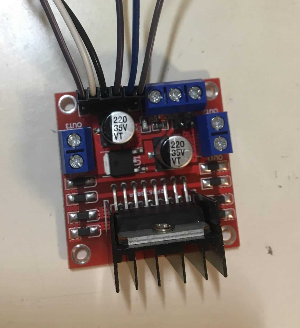
Motor Driver/ DC Motors

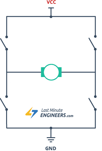
Motor drivers help the Arduino to control DC motors. The component takes a low-current control signal and then turns it into a higher-current signal that can drive a motor. For my project, I used the L298N board as it is a dual motor driver than works with Arduino. There are two main parts to a motor driver; PWM and H-bridge control. The PWM is the signals sent to the enable pins on the motor driver from the PWM pins on the Arduino. By sending a carrying input voltage, the speed of the motors can change from low to high and goes from a range of 0 to 255. The signal is converted to a voltage. The H-bridge controls the rotation the motors are spinning in, which therefore controls which direction the entire car moves. The use of four transistors in an H format with the motor in the middle controls the polarity, which is the direction of the current. Closing a pair of the transistors will cause the current to flow in one direction, turning the motor one way. Closing the opposite pair of transistors will cause the current to flow in the opposite direction, and the motor will rotate the other way. On the physical motor driver, there are output pins where the motor connected to the motor driver, which completes the H-bridge circuit. The control pins at the front control the rotation and speed of the motors. They connect to the digital pins on the Arduino to receive signals, which then tell the motor driver which pair of transistors to open and close to get the specified rotation. The enable pins also control the speed of the motors. The combination of high-low signals to the motor will give its rotation direction, and changing the direction of both the motors will give specific movements. Understanding the motor driver was important in figuring out how to control the car and achieve the movements from the app.

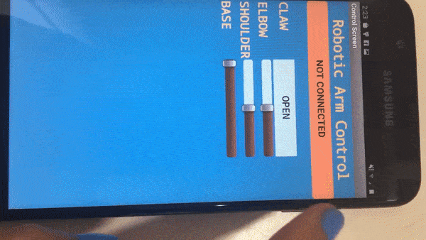
In the next version of my app for this milestone, I added some new components to control the new features of my project. There is autonomous buttons and a party lights button added to the top, as well as a button to return to the manual mode. To control the car, there are arrow buttons at the bottom.
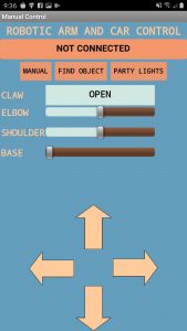
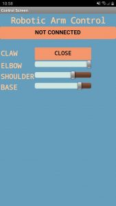
This is the design screen of the app. It has all the different components that the user can interact with.
These are the buttons to control the car movements. While it is pressed down, the movement is activated through the Arduino. The movement will stop once the button is released. The movements are currently not working with the code.
These are the buttons to control which mode the app is in, which is either manual or autonomous. There is also a part lights button to have a fun light show.
Second Milestone
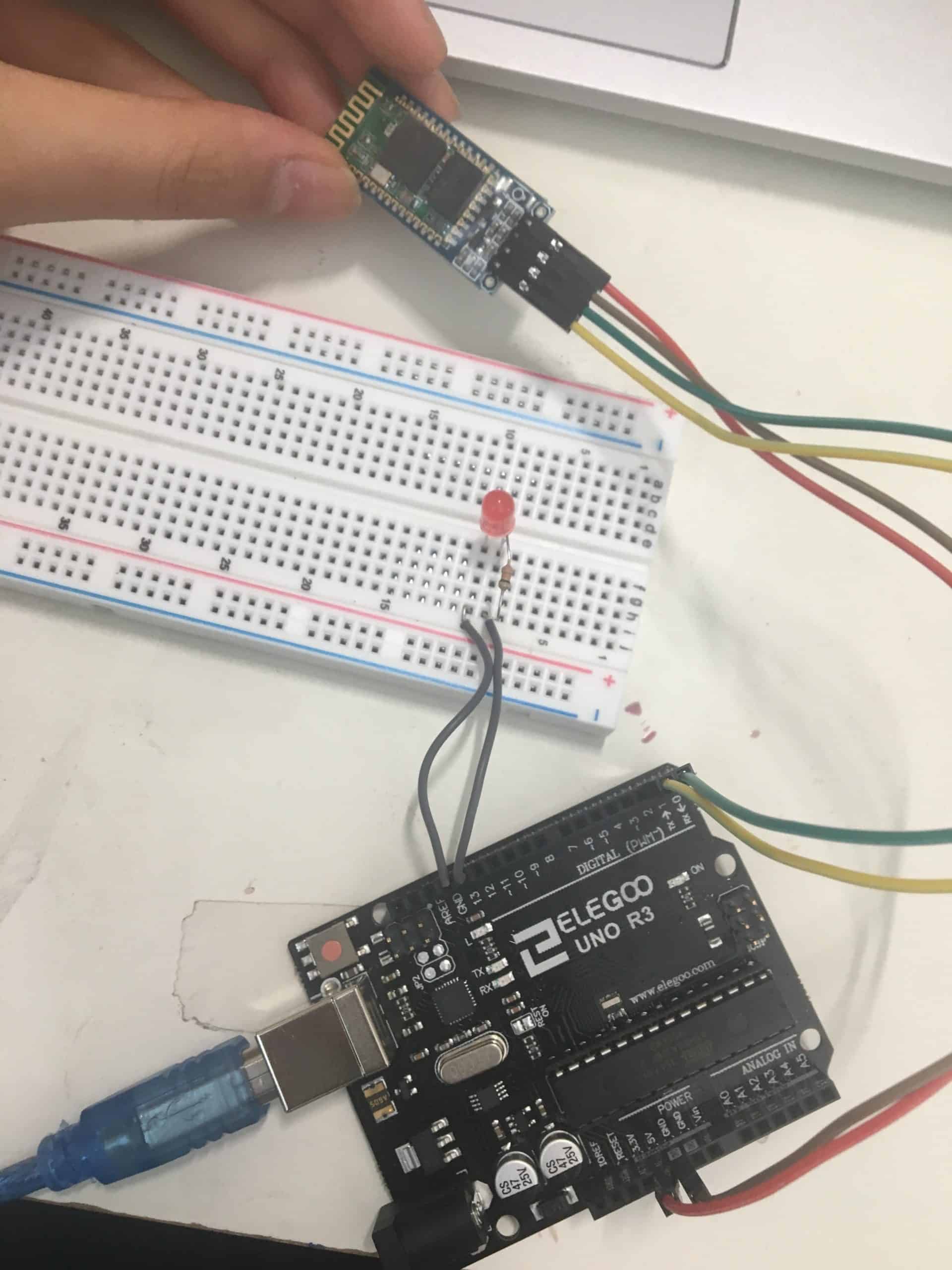
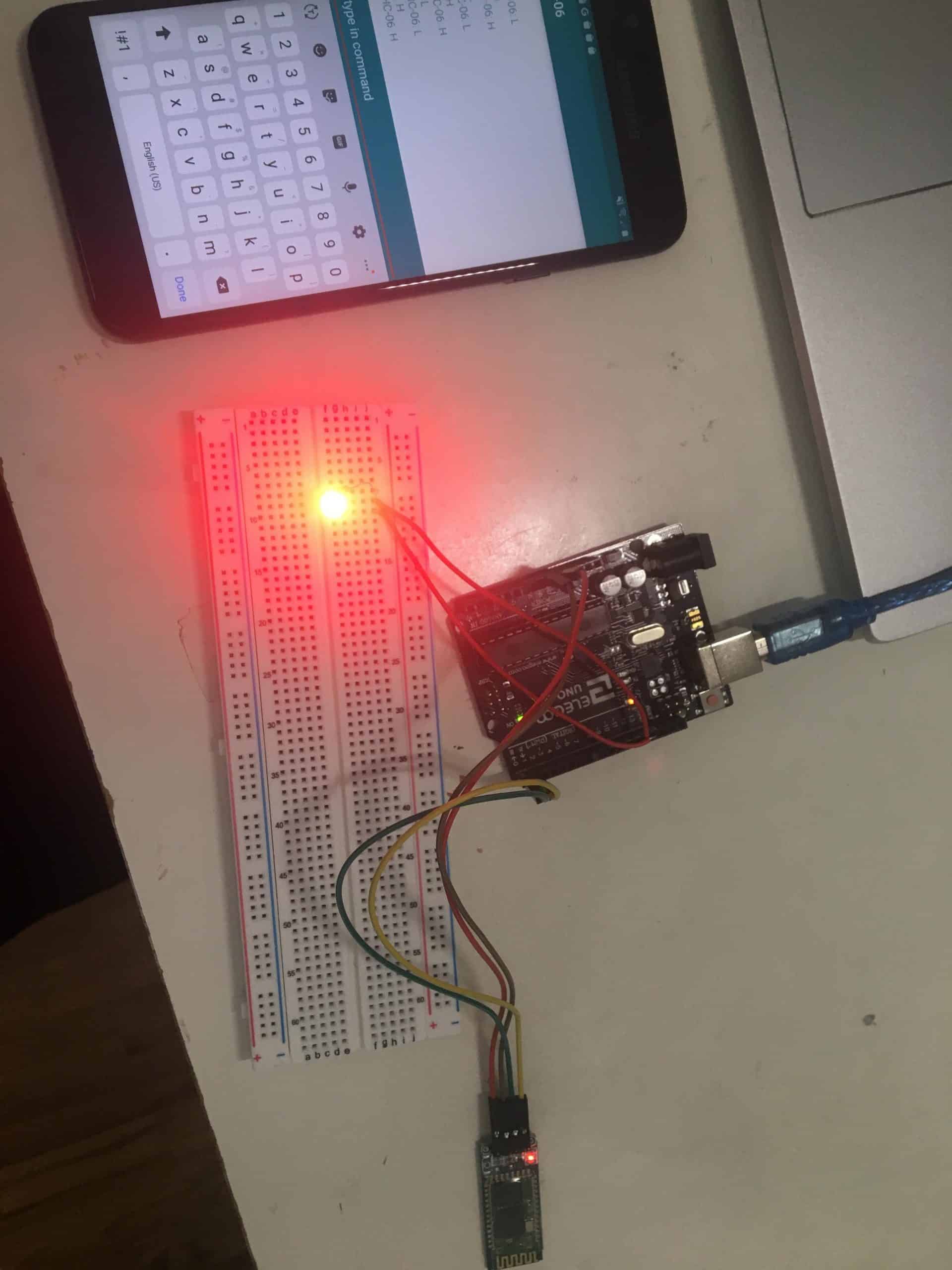
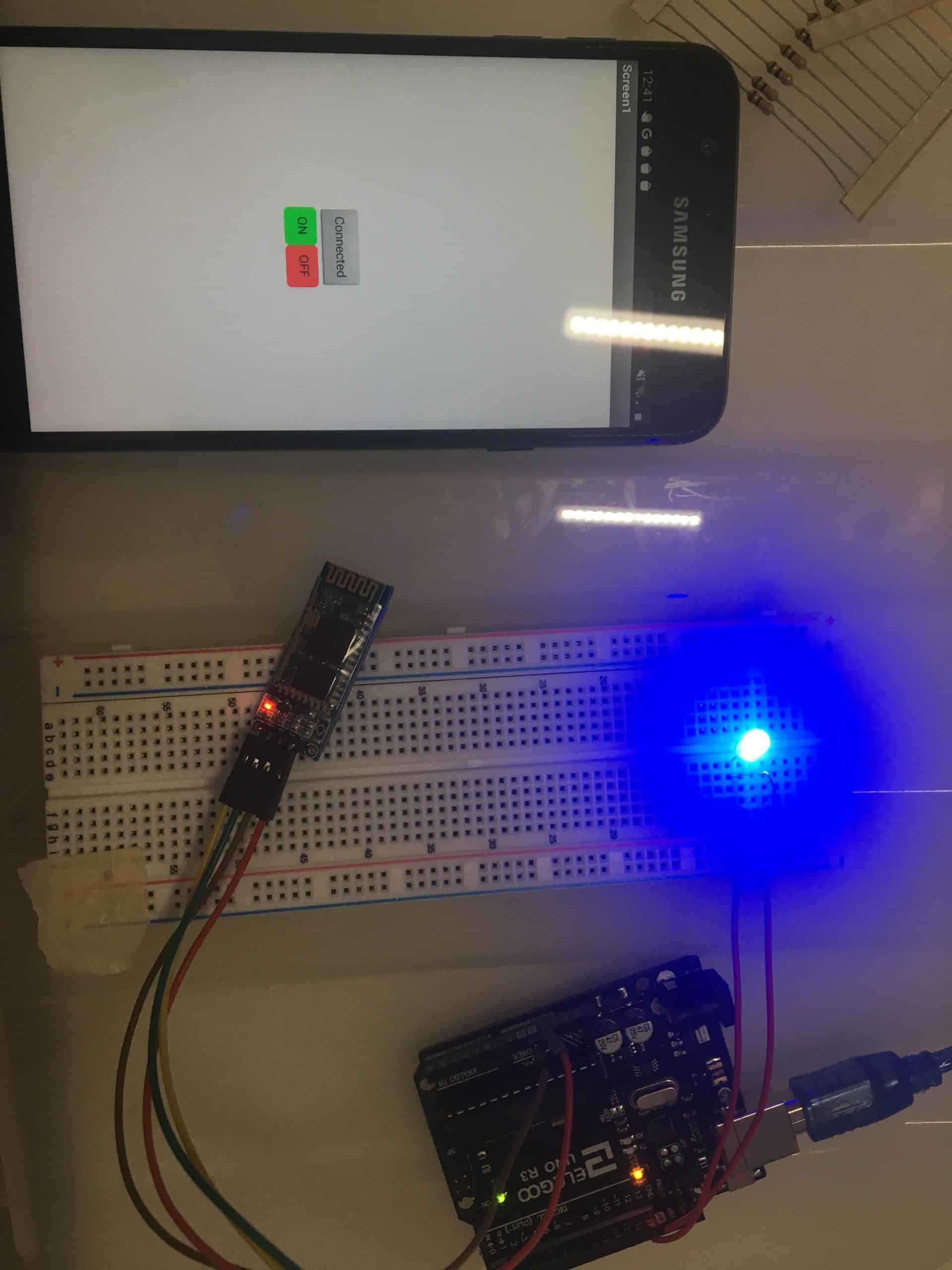
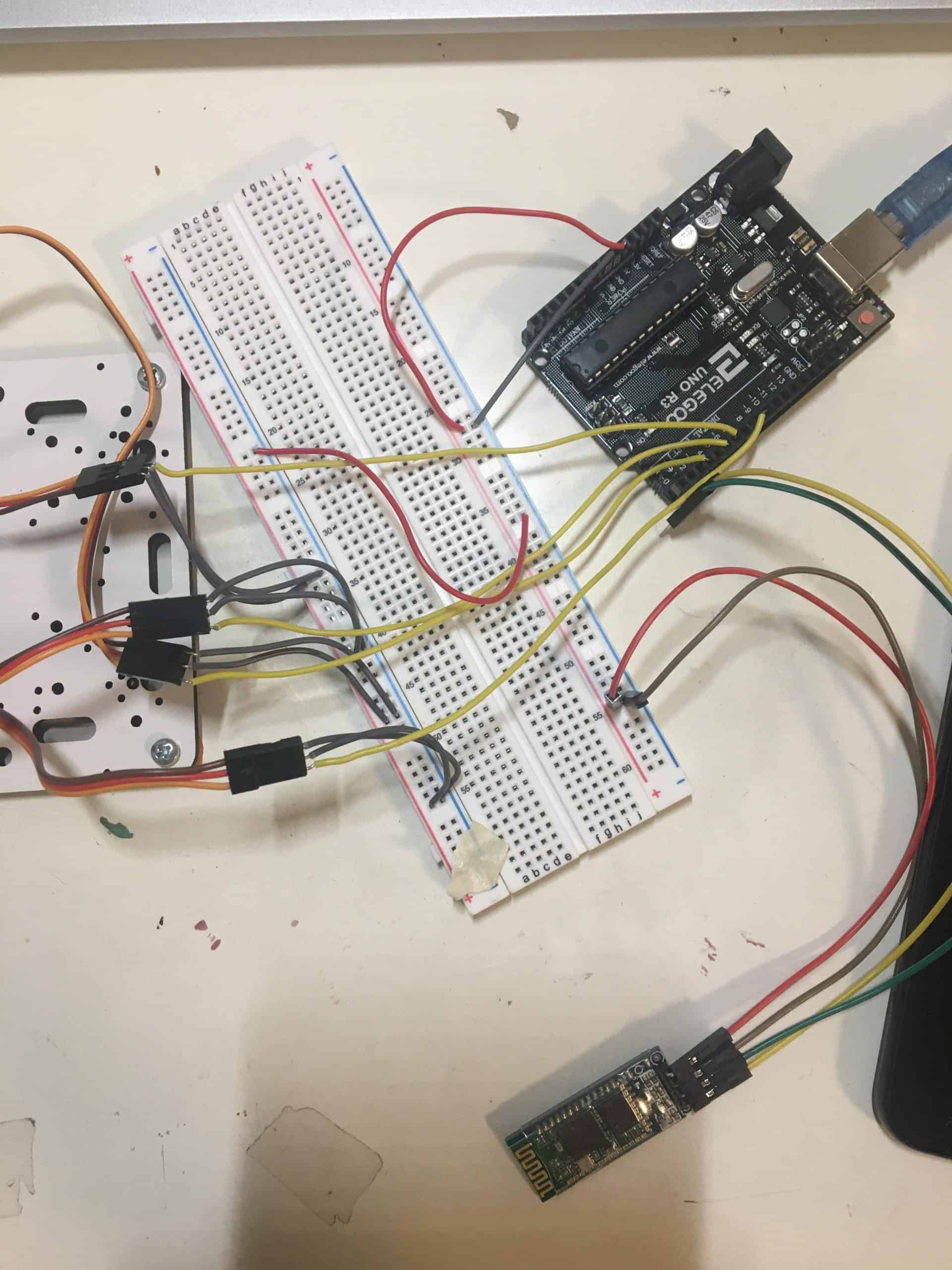
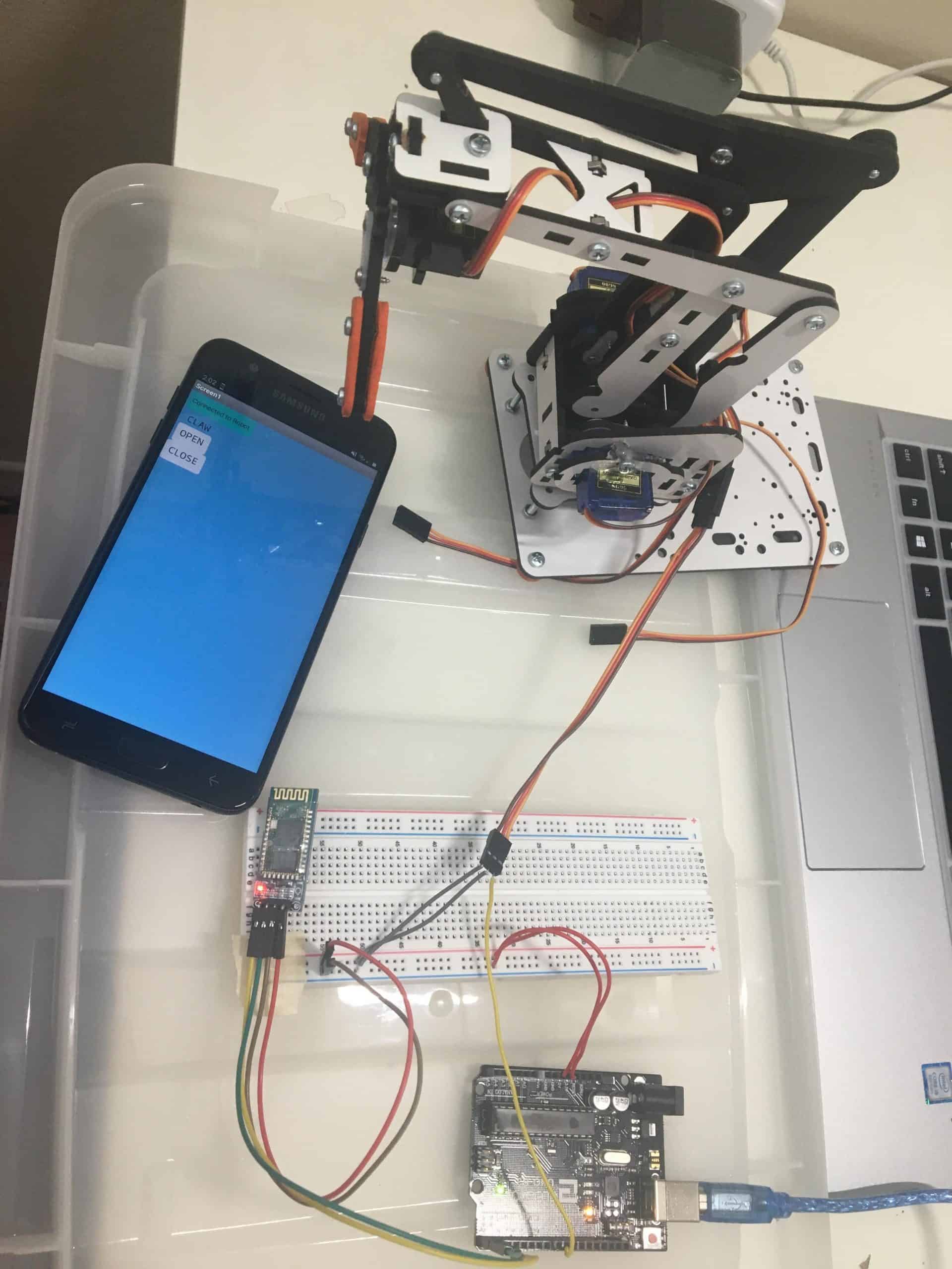
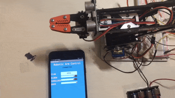
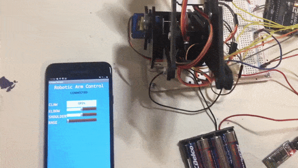
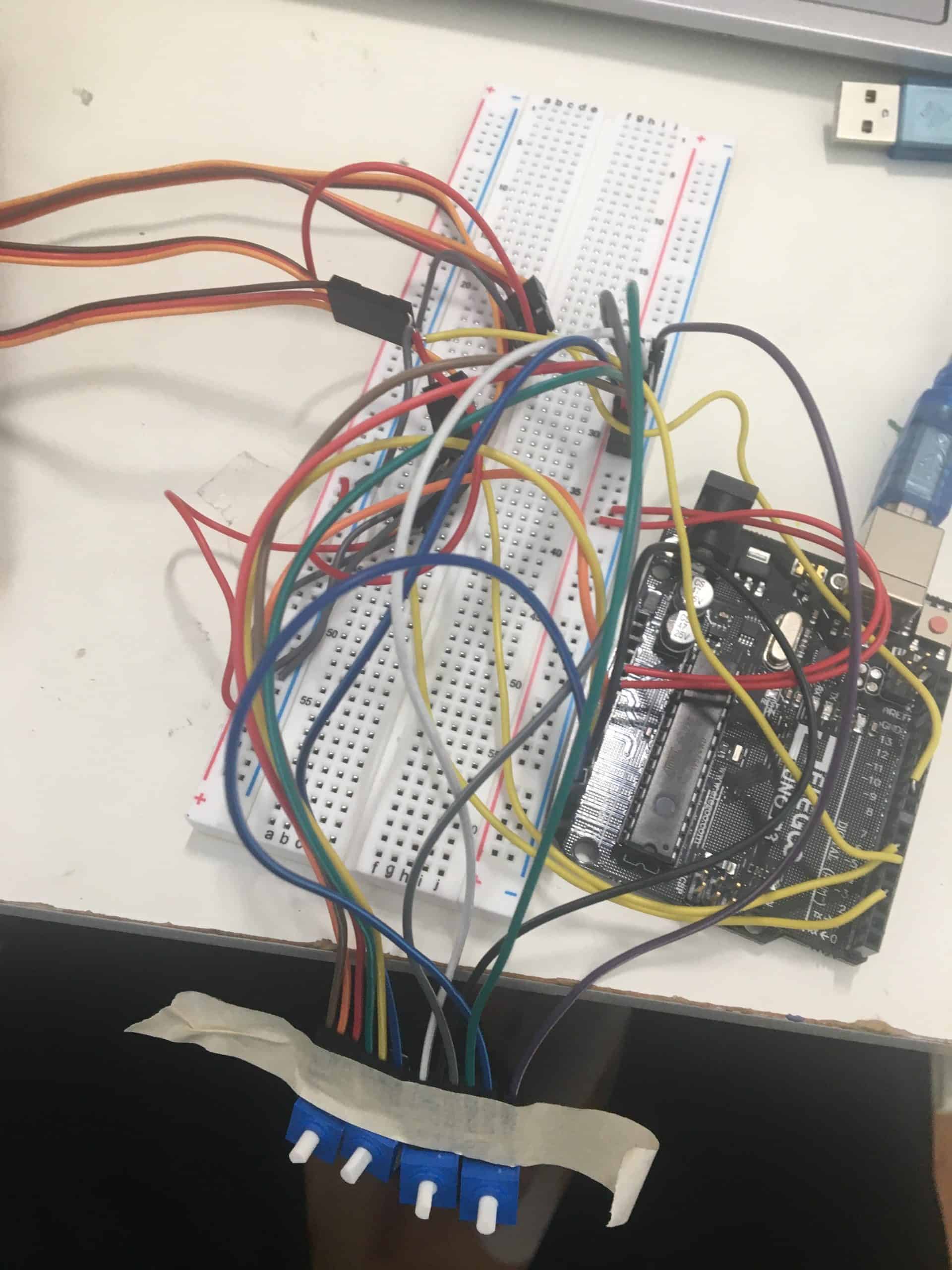
For my second milestone in this project, I changed the control system from potentiometers to Bluetooth control through an app. I used the MIT App Inventor to customize my own app and add components to control the robotic arm manually. Before working on the MIT App Inventor, I had to connect a Bluetooth HC 06 module to my circuit with the microservos and Arduino. Adding the code the receive the data from the module and have command blocks to change different servos was the biggest change in my code for this milestone, and required an understanding about string manipulation as well as learning about how Bluetooth modules communicate. After initially setting up an app to control an LED as practice with MIT App Inventor and Bluetooth, I was able to make an app that controlled all the servos through sliders and buttons.
In addition to completing the Bluetooth modification, I decided to implement some sensors to the robotic arm to add more customization to my project. Within the milestone, I added an ultrasonic sensor to the claw of the arm to create some autonomous features. The ultrasonic sensor measures the distance of the object around the sensor, returning a value that can be used to determine how far away something is. Using this information, the claw servo will automatically be set to an open position if the ultrasonic sensor detects something that is less than 10 cm away from the sensor. I decided to implement this modification as a pathway towards future modifications of fully autonomous control of the robotic arm. For my next milestone, I am going to build a car chassis base that the robotic arm can attach to and implement a car control in my app so the robotic arm can drive around. I also am going to add different modes of control to my app, such as sound control and autonomous control.
During this milestone, the majority of the work was getting the Bluetooth to work, making an app to control the robotic arm through Bluetooth, and attaching an ultrasonic sensor to the claw. With the Bluetooth, I had issues with getting the Arduino code to upload to the Arduino when I had the Bluetooth plugged in. Looking further into the documentation about the Bluetooth module, I found that the TX and RX pins on the Bluetooth should only be plugged in after the code is uploaded to the Arduino. This was an important piece of information that I had overlooked when seeing how to work with the Bluetooth. The TX and RX pins on the Arduino are used to also communicate with the computer to upload code. By plugging in the Bluetooth module beforehand, the Arduino could not receive the code from the computer, so simply waiting for the code to uploaded before plugging in those pins fixed the issue I had with the Bluetooth.
Working with the app inventor was a challenge, as I had to learn more about the different features and components, as well as how to use the control structures to send data. Figuring out how to send text to the Bluetooth when a slider or button was changed and creating the best layout for the screen took a significant amount of time. Viewing tutorials about different ways to have features helped to pick up new ideas and implement them. An issue I had with the slider values printing out unusual values was solved when I learned that sliders return decimals, not integers, so learning about the different components helped to reach the goal of using Bluetooth control.
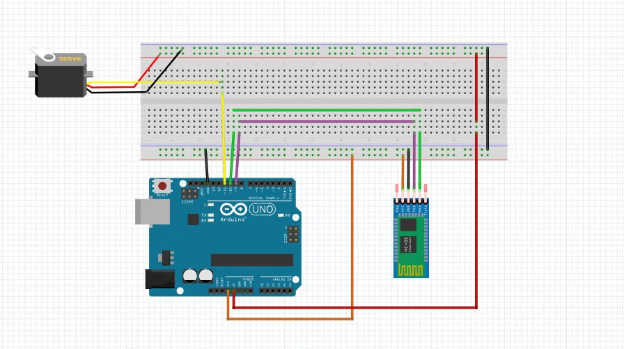
Bluetooth Module
The Bluetooth HC 06 module is how I was able to control the robotic arm from an Android app. The module works on serial communication, so the Android app sends serial data to the module when buttons or sliders are used. The Bluetooth module is connected to the transmit (TX) and receive (RX) pins on the Arduino to send and receive data to the Arduino and computer. The code on the computer takes in the received data from the Arduino and checks specific elements to control the servos and write different angles to the servos. The information from the Android app is sent to the Bluetooth module and then transmitted to the Arduino to control the servos. If the connection between the Bluetooth module and the app is lost, the Bluetooth module transmits a signal to the app to relay that information, and that change is displayed on the app as Not Connected. In my project, I started with a pre-downloaded app to control an LED to learn the basics about using a Bluetooth module. After understanding and grasping the Bluetooth concept, I was able to make my own app using the MIT App Inventor to control the simple LED circuit, and eventually built the project to control the servos and include more user interface. The process of learning about the Bluetooth module and going from serial inputs to user components to send the serial data helped to develop the skills needed to fix problems with the Bluetooth and controls.
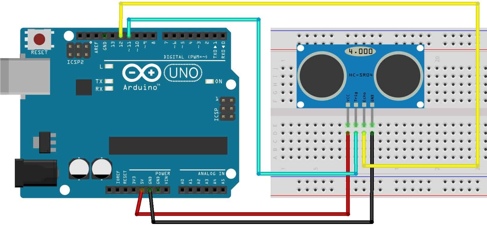
Ultrasonic Sensor
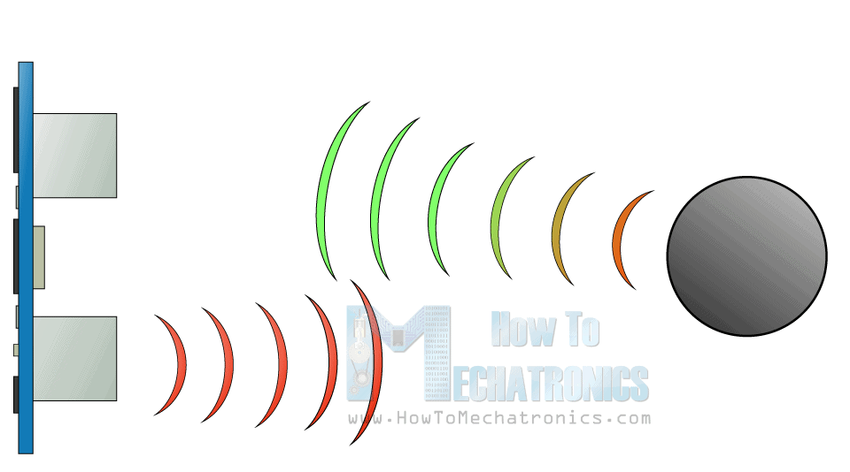
The ultrasonic sensor is used to measure the distance from objects around. The two circles in front of the sensor transmit and receive ultrasound waves, which are used to detect how far away an object is. The sensor emits the waves and then receives the waves once they hit an object and bounce back. The Trig pin of the sensor generates the waves and can be set to high or low for certain amounts of time. The length of the pulse is returned by the Echo pin of the sensor by reading the received waves. The formula Distance = Speed x Time can be used with the speed of sound to calculate the distance between the sensor and the object. These pins are connected to the PWM pins on the Arduino, so the length of the pulses can be controlled by the Arduino. For my project, I used the ultrasonic sensor to detect if an object is within a certain distance, which is measuring the length of the waves emitted and received. If the condition is met, then the claw servo is immediately written to an open position. This means that if an object is within the range, the arm will automatically open up and grab the object, providing another dimension of usability to the project.
The program I used to develop my app was MIT App Inventor. The two parts of the screen design for the user interface and the control structures that send the serial data to the Bluetooth module when the components are used. I was able to customize and layout and colors of the app to my liking with the different options the program has.
This is the design screen in MIT App Inventor. There are buttons, sliders, and list pickers that the user can interact with to control the robotic arm. The button and sliders are to control the servos, and the list picker at the top is to connect the app to the robotic arm through the Bluetooth module.
As the user interacts with the sliders and buttons to control the arm, the app needs to communicate information to the Arduino in order to move the servos in the specified direction. For the claw servo, an open and close button is used to set the servo angle to an open or closed position. This is down by sending a string to the Bluetooth module and the Arduino. In the code used for the robotic arm, the string is read for specific elements and uses if-else blocks to write to the servo to a specific angle. For the other servos that control the joint movements of the arm, sliders are used to have a variety of angles that can be written to. The thumb position of the slider is sent to the Bluetooth module with specific elements to identify the servo being changed. The code takes this string and reads the specific elements to change the servo accordingly. Using the blocks to control the user interface, the app can communicate with the Arduino and control the robot remotely.
In order to communicate with the Arduino, the app uses blocks to control different actions. These blocks show the blocks used to connect the app to the Bluetooth muddle using the list picker element. The Bluetooth module is shown in a list and the color of the component changes to indicate to the user that the robot is connected and ready to control.
First Milestone
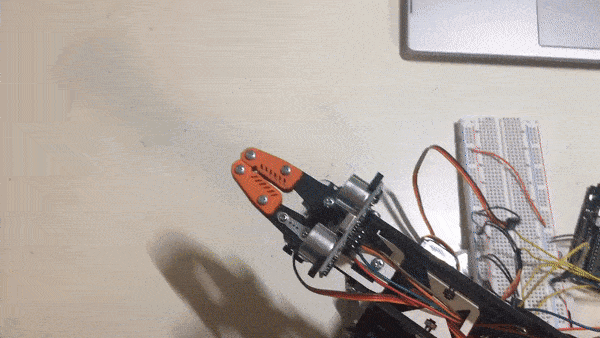
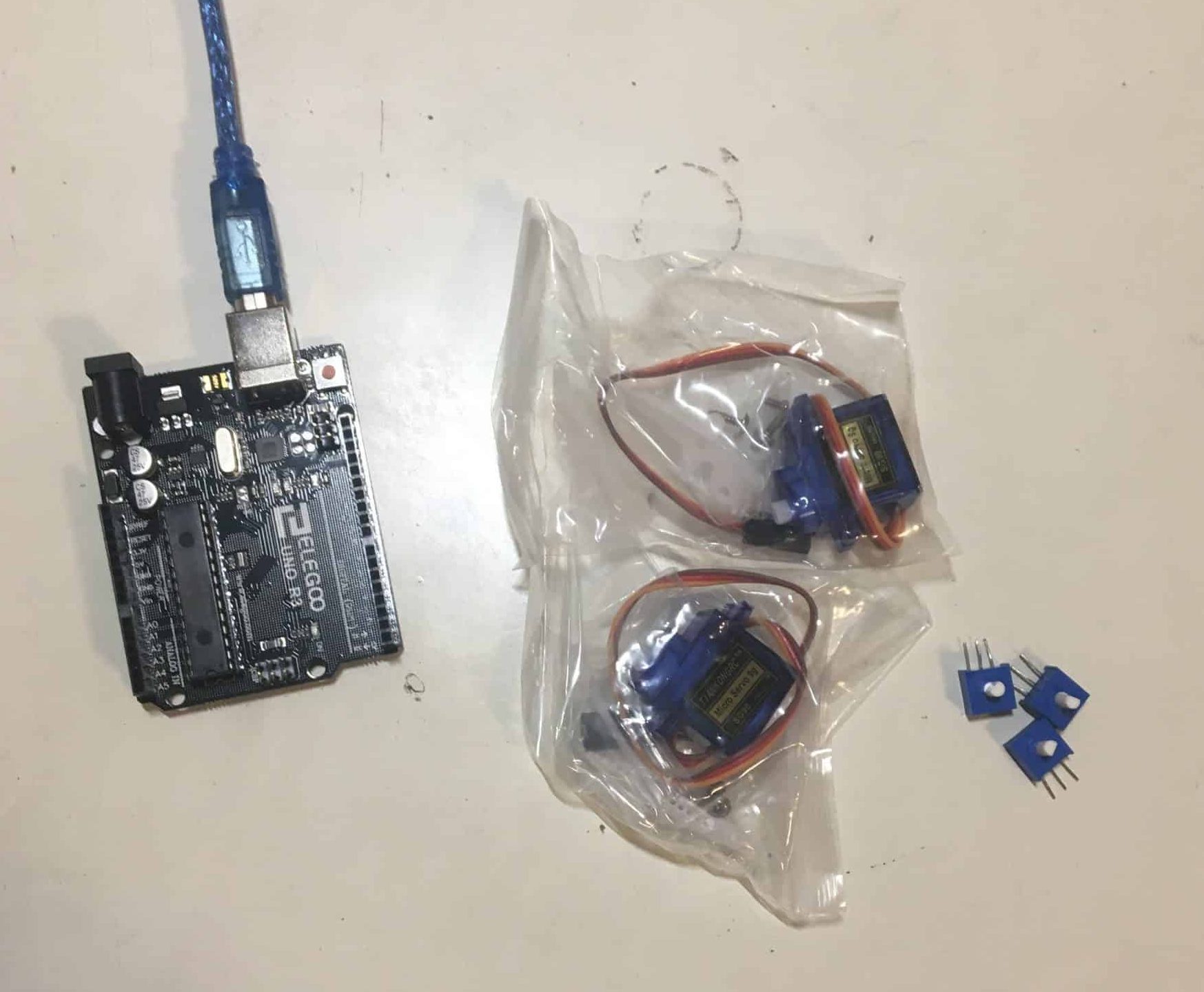
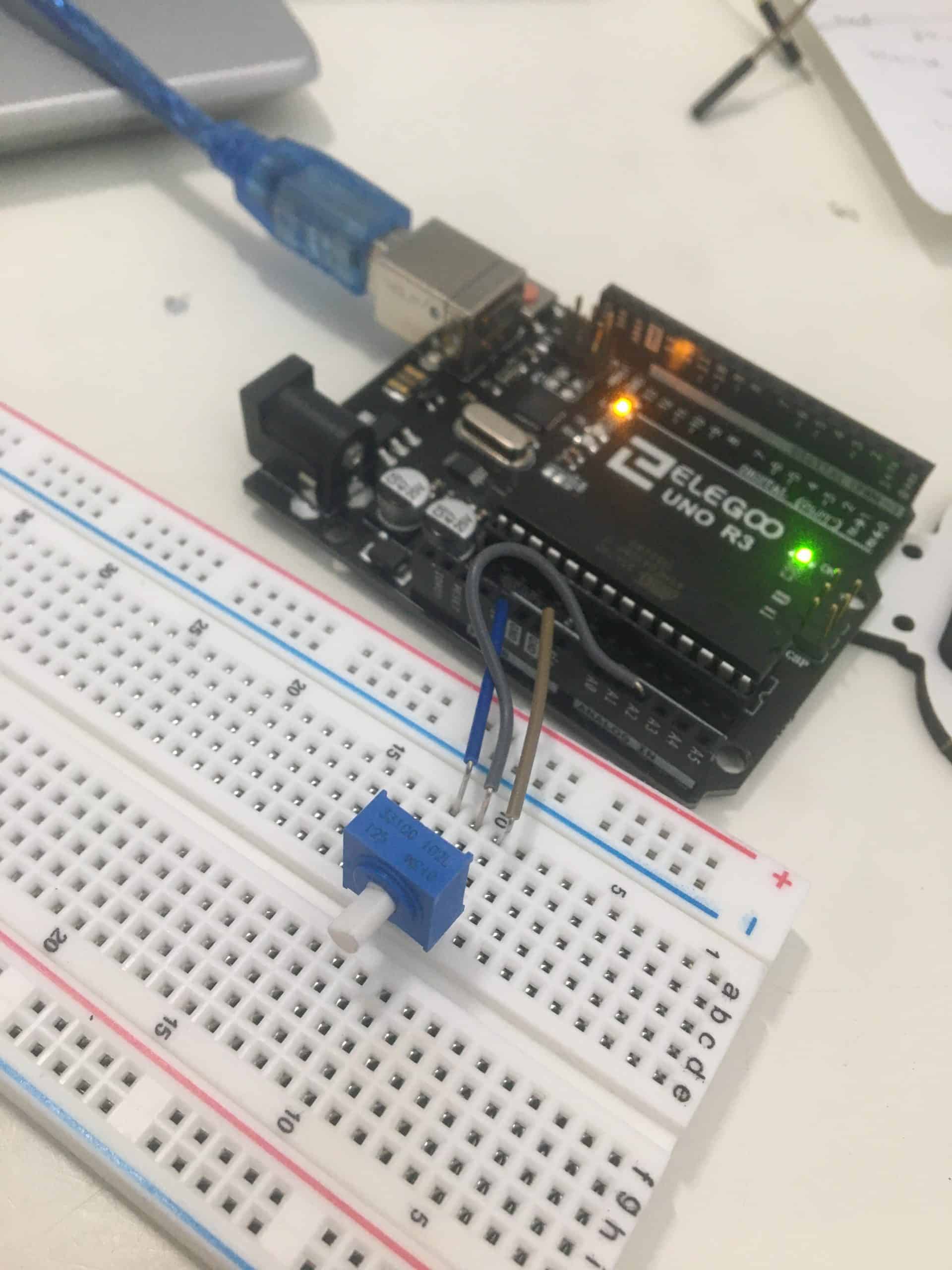
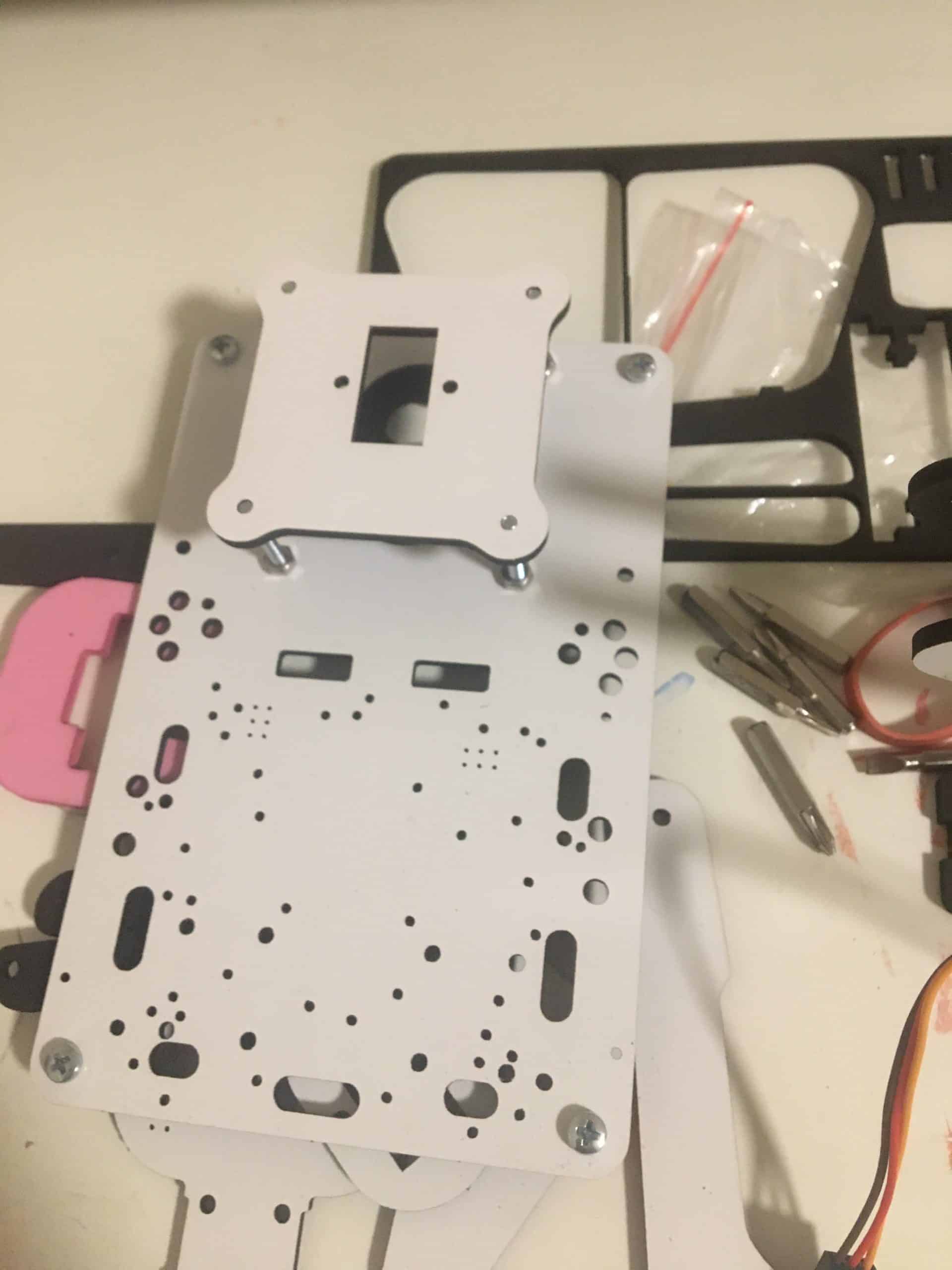
My first milestone for this project was assembling the basic arm with the claw and adding the mircoservos to each joint of the robot that had to move. To assemble the arm, I used the different parts, bolts, and nuts to connect all the pieces. The microservos were all connected to the Arduino UNO through jumper wires in the breadboard. The servos control the base, shoulder, elbow, and claw movements of the arm. There are also potentiometers that control the servos. In order to control the servos with the potentiometers, I had to code the Arduino by connecting the components to the pins, reading the value given by the potentiometers, and changing the angle of the servo using the returned value of the potentiometer. Servos are controlled by electrical pulses, and the angle of the servo is therefore determined by the duration of a pulse. The value given by the potentiometer changes the length of the pulse and the angle of the servo, moving the joint of the robot. The potentiometers work by changing the resistance through a wiper inside the component. The servos and potentiometers are connected to the Arduino 5V power and the ground pin of the Arduino. By connecting the potentiometers to the analog pins, an integer value can be read from the potentiometer and used to change the servo angle. The servos are connected to the Digital pins to control the length of the pulses, and the average input voltage is adjusted to control the position of the servo. For my next milestone, I am going to working modifying the control system to be controlled through an app.
While working towards this milestone, I faced a few challenges with the components of the arm. The servos had problems with staying in the angle that they were written to, causing them to shift around instead of staying in place. This was a problem as the robot arm would move erratically, preventing it from performing its task. After researching this issue and receiving guidance, I learned that instability in the power and potentiometer value was causing the pulses to change. My approach to solving the problem was using capacitors to store the energy and smooth the output pulse to the servo, add an external battery to provide a steady supply of energy, and change the code to input a stable value into the servo. Using the external battery was the best option as it was easier to provide a stable energy source without excessively tampering with the servos. In addition, changing the code to compare the potentiometer with an old value from 1 second ago also helped to reduce the jittering by stabilizing the written value to the servo. While trying to adjust one of the servos on the arm, the servo collar broke. I was able to use the hot glue gun to fix the piece, and the process taught me to not only be careful with the pieces I am using but also to be prepared for some pieces to break in the building process.