∞ Gesture Controlled Car ∞
In this project I built a car and wired motors and a battery to power it. Then I uploaded code to program the car. My next steps are to connect my bluetooth module to the car and the master bluetooth module to the remote arduino, which makes the car gesture controlled. Think, Power Rangers megazord.
Engineer
Lailah B.
Area of interest
Robotics, computer programing
School
Success Academy High School of Liberal Arts
Grade
Incoming Sophomore
Final Milestone
Arduino Uno
wires
Ultra sonic sensor
Servo
ultrasonic sensor
Serial Monitor


*insert code here*
Servo
Serial Monitor

*insert code here*
Integrate both codes
Serial Monitor

*insert code here*
Second Milestone
Arduino Uno
Arduino Nano
nrf24l01 module (2)
accelerometer
bread board
wires
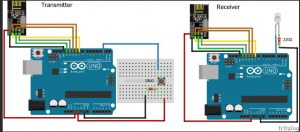
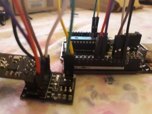
First I had to set up and connect both my nrf24l01 modules. One was the transmitter and the other was the receiver.
The Transmitter was connected to the Arduino Nano and the Receiver was connected to the Arduino Uno.
The nrf’s use radio waves that communicate like walkie – talkies.


connection guide
Arduino Nano/Uno -> nrf24l01
3.3v -> VCC/VIN
GND -> GND
8 -> CSN
7 -> CE
13 -> SCK
11 -> MOSI
12 -> MISO
Serial Monitor

-
/* -
* Arduino Wireless Communication Tutorial -
* Example 1 - Transmitter Code -
* -
* by Dejan Nedelkovski, www.HowToMechatronics.com -
* -
* Library: TMRh20/RF24, https://github.com/tmrh20/RF24/ -
*/ -
#include <SPI.h> -
#include <nRF24L01.h> -
#include <RF24.h> -
RF24 radio(7, 8); // CE, CSN
-
const byte address[6] = "00001";
-
void setup() {
-
radio.begin();
-
radio.openWritingPipe(address);
-
radio.setPALevel(RF24_PA_MIN);
-
radio.stopListening();
-
} -
void loop() {
-
const char text[] = "Hello World";
-
radio.write(&text, sizeof(text));
-
delay(1000);
-
}
-
/* -
* Arduino Wireless Communication Tutorial -
* Example 1 - Receiver Code -
* -
* by Dejan Nedelkovski, www.HowToMechatronics.com -
* -
* Library: TMRh20/RF24, https://github.com/tmrh20/RF24/ -
*/ -
#include <SPI.h> -
#include <nRF24L01.h> -
#include <RF24.h> -
RF24 radio(7, 8); // CE, CSN
-
const byte address[6] = "00001";
-
void setup() {
-
Serial.begin(9600);
-
radio.begin();
-
radio.openReadingPipe(0, address);
-
radio.setPALevel(RF24_PA_MIN);
-
radio.startListening();
-
} -
void loop() {
-
if (radio.available()) {
-
char text[32] = "";
-
radio.read(&text, sizeof(text));
-
Serial.println(text);
-
} -
}
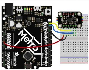
Then I had to set up my accelerometers, by plunging it in my Arduino Nano. The accelerometer measures angles and positions, which is important for gesture control because its based on hand movement, and the car will recognize the gesture into direction.

Connections Guide:
Accelerometer -> Arduino
VCC -> 3.3 V / 5 V (better)
GND -> GND
SCL -> A5
SDA -> A4
Serial Monitor

-
// Basic demo for accelerometer readings from Adafruit MPU6050 -
-
#include <Adafruit_MPU6050.h>
-
#include <Adafruit_Sensor.h>
-
#include <Wire.h>
-
-
Adafruit_MPU6050 mpu;
-
-
void setup(void) {
-
Serial.begin(115200);
-
while (!Serial)
-
delay(10); // will pause Zero, Leonardo, etc until serial console opens
-
-
Serial.println("Adafruit MPU6050 test!");
-
-
// Try to initialize! -
if (!mpu.begin()) {
-
Serial.println("Failed to find MPU6050 chip");
-
while (1) {
-
delay(10);
-
} -
} -
Serial.println("MPU6050 Found!");
-
-
mpu.setAccelerometerRange(MPU6050_RANGE_8_G);
-
Serial.print("Accelerometer range set to: ");
-
switch (mpu.getAccelerometerRange()) {
-
case MPU6050_RANGE_2_G:
-
Serial.println("+-2G");
-
break;
-
case MPU6050_RANGE_4_G:
-
Serial.println("+-4G");
-
break;
-
case MPU6050_RANGE_8_G:
-
Serial.println("+-8G");
-
break;
-
case MPU6050_RANGE_16_G:
-
Serial.println("+-16G");
-
break;
-
} -
mpu.setGyroRange(MPU6050_RANGE_500_DEG);
-
Serial.print("Gyro range set to: ");
-
switch (mpu.getGyroRange()) {
-
case MPU6050_RANGE_250_DEG:
-
Serial.println("+- 250 deg/s");
-
break;
-
case MPU6050_RANGE_500_DEG:
-
Serial.println("+- 500 deg/s");
-
break;
-
case MPU6050_RANGE_1000_DEG:
-
Serial.println("+- 1000 deg/s");
-
break;
-
case MPU6050_RANGE_2000_DEG:
-
Serial.println("+- 2000 deg/s");
-
break;
-
} -
-
mpu.setFilterBandwidth(MPU6050_BAND_21_HZ);
-
Serial.print("Filter bandwidth set to: ");
-
switch (mpu.getFilterBandwidth()) {
-
case MPU6050_BAND_260_HZ:
-
Serial.println("260 Hz");
-
break;
-
case MPU6050_BAND_184_HZ:
-
Serial.println("184 Hz");
-
break;
-
case MPU6050_BAND_94_HZ:
-
Serial.println("94 Hz");
-
break;
-
case MPU6050_BAND_44_HZ:
-
Serial.println("44 Hz");
-
break;
-
case MPU6050_BAND_21_HZ:
-
Serial.println("21 Hz");
-
break;
-
case MPU6050_BAND_10_HZ:
-
Serial.println("10 Hz");
-
break;
-
case MPU6050_BAND_5_HZ:
-
Serial.println("5 Hz");
-
break;
-
} -
-
Serial.println("");
-
delay(100);
-
} -
-
void loop() {
-
-
/* Get new sensor events with the readings */ -
sensors_event_t a, g, temp;
-
mpu.getEvent(&a, &g, &temp);
-
-
/* Print out the values */ -
Serial.print("Acceleration X: ");
-
Serial.print(a.acceleration.x);
-
Serial.print(", Y: ");
-
Serial.print(a.acceleration.y);
-
Serial.print(", Z: ");
-
Serial.print(a.acceleration.z);
-
Serial.println(" m/s^2");
-
-
Serial.print("Rotation X: ");
-
Serial.print(g.gyro.x);
-
Serial.print(", Y: ");
-
Serial.print(g.gyro.y);
-
Serial.print(", Z: ");
-
Serial.print(g.gyro.z);
-
Serial.println(" rad/s");
-
-
Serial.print("Temperature: ");
-
Serial.print(temp.temperature);
-
Serial.println(" degC");
-
-
Serial.println("");
-
delay(500);
-
}
The last step was to write a code that combined the nrf module and accelerometer, for each receiver and transmitter Arduino.
This is so the Nrf module can transmit and receive values form the accelerometer.
*Notice how the serial monitor reads “turn right” and “move backward”, down below.
Serial Monitor

#include <SPI.h>
#include <nRF24L01.h>
#include <RF24.h>
#include <Adafruit_MPU6050.h>
#include <Adafruit_Sensor.h>
#include <Wire.h>

RF24 radio(7, 8); // CE, CSN

const byte address[6] = "00001";

char gesture = '0'; //by default, the car is not moving

Adafruit_MPU6050 mpu;

void setup() {

radio.begin();
radio.openWritingPipe(address);
radio.setPALevel(RF24_PA_MIN);
radio.stopListening();

Serial.begin(115200);
while (!Serial)
delay(10); // will pause Zero, Leonardo, etc until serial console opens

Serial.println("Adafruit MPU6050 test!");

// Try to initialize!
if (!mpu.begin()) {
Serial.println("Failed to find MPU6050 chip");
while (1) {
delay(10);
}
}
Serial.println("MPU6050 Found!");

mpu.setAccelerometerRange(MPU6050_RANGE_8_G);
Serial.print("Accelerometer range set to: ");
switch (mpu.getAccelerometerRange()) {
case MPU6050_RANGE_2_G:
Serial.println("+-2G");
break;
case MPU6050_RANGE_4_G:
Serial.println("+-4G");
break;
case MPU6050_RANGE_8_G:
Serial.println("+-8G");
break;
case MPU6050_RANGE_16_G:
Serial.println("+-16G");
break;
}
mpu.setGyroRange(MPU6050_RANGE_500_DEG);
Serial.print("Gyro range set to: ");
switch (mpu.getGyroRange()) {
case MPU6050_RANGE_250_DEG:
Serial.println("+- 250 deg/s");
break;
case MPU6050_RANGE_500_DEG:
Serial.println("+- 500 deg/s");
break;
case MPU6050_RANGE_1000_DEG:
Serial.println("+- 1000 deg/s");
break;
case MPU6050_RANGE_2000_DEG:
Serial.println("+- 2000 deg/s");
break;
}

mpu.setFilterBandwidth(MPU6050_BAND_21_HZ);
Serial.print("Filter bandwidth set to: ");
switch (mpu.getFilterBandwidth()) {
case MPU6050_BAND_260_HZ:
Serial.println("260 Hz");
break;
case MPU6050_BAND_184_HZ:
Serial.println("184 Hz");
break;
case MPU6050_BAND_94_HZ:
Serial.println("94 Hz");
break;
case MPU6050_BAND_44_HZ:
Serial.println("44 Hz");
break;
case MPU6050_BAND_21_HZ:
Serial.println("21 Hz");
break;
case MPU6050_BAND_10_HZ:
Serial.println("10 Hz");
break;
case MPU6050_BAND_5_HZ:
Serial.println("5 Hz");
break;
}

Serial.println("");
delay(100);


}

void loop() {

/* Get new sensor events with the readings */
sensors_event_t a, g, temp;
mpu.getEvent(&a, &g, &temp);


/* Print out the values */
Serial.print("Acceleration X: ");
Serial.print(a.acceleration.x);
Serial.print(", Y: ");
Serial.print(a.acceleration.y);
Serial.print(", Z: ");
Serial.print(a.acceleration.z);
Serial.println(" m/s^2");

Serial.print("Rotation X: ");
Serial.print(g.gyro.x);
Serial.print(", Y: ");
Serial.print(g.gyro.y);
Serial.print(", Z: ");
Serial.print(g.gyro.z);
Serial.println(" rad/s");

//Serial.print("Temperature: ");
//Serial.print(temp.temperature);
//Serial.println(" degC");

//Serial.println("");
//delay(500);

//new

//add code here to convert the accelerometer data into a command for the robot
//forward gesture occures when acceleration.x is greater than 4
//move backwards gesture occurs when
if (a.acceleration.x == 0.0)
{
gesture = 0;
Serial.println("stop moving");
radio.write(&gesture, sizeof(gesture));
}
if (a.acceleration.x > 4.0)
{
gesture = 1;
Serial.println("move foward");
radio.write(&gesture, sizeof(gesture));
}

//move backwards gesture occurs when
if (a.acceleration.x < 2.0)
{
gesture = 2;
Serial.println("move backward");
radio.write(&gesture, sizeof(gesture));
}

//move right gesture occurs when
if (a.acceleration.x > -2.0)
{
gesture = 3;
Serial.println("turn right");
radio.write(&gesture, sizeof(gesture));

}
//move left gesture occurs when
if (a.acceleration.x > 10.0)
{
gesture= 4;
Serial.println("turn left");
radio.write(&gesture, sizeof(gesture));
}
//send the gesture signal to the Arduino Uno
}
/*
* Arduino Wireless Communication Tutorial
* Example 1 - Receiver Code
*
* by Dejan Nedelkovski, www.HowToMechatronics.com
*
* Library: TMRh20/RF24, https://github.com/tmrh20/RF24/
*/

#include <SPI.h>
#include <nRF24L01.h>
#include <RF24.h>
#include <L298N.h>

RF24 radio(7, 8); // CE, CSN

const byte address[6] = "00001";
int value=-1;

//pin definition
#define ENa 5
#define IN1 2
#define IN2 6

#define ENb 3
#define IN3 9
#define IN4 4
//create a motor instance
L298N motor(ENa, IN1, IN2);
L298N motor2(ENb, IN3,IN4 );
//motor 2= left output 3&4
//motor= right output 1&2
//max speed = 255
void setup() {
Serial.begin(9600);
radio.begin();
radio.openReadingPipe(0, address);
radio.setPALevel(RF24_PA_MIN);
radio.startListening();
}

void loop() {
if (radio.available()) {
// char text[32] = "";

radio.read(&value, sizeof(value));
Serial.println(value);

if (value == 0)
{
//motors should all be off
motor.setSpeed(0);
motor2.setSpeed(0);
Serial.println ("Motors off");
}
else if (value == 1)
{
//motors should drive forward
//add code here for motors to drive forward
motor.setSpeed(250);
motor2.setSpeed(250);
motor.forward();
motor2.forward();
Serial.println ("Driving foward");
}
else if (value == 2)
{
//motors should drive backward
//add code here for motors to drive backward

motor.setSpeed(200);
motor2.setSpeed(200);
motor.backward();
motor2.backward();
Serial.println ("Driving backward");
}
else if (value == 3)
{
//motors should drive right

motor.setSpeed(250);
motor2.setSpeed(0);
motor.forward();
motor2.forward();
Serial.println ("turning right");
}
else if (value == 4)
{

//motors should drive left
motor.setSpeed(0);
motor2.setSpeed(250);
motor.forward();
motor2.forward();
Serial.println ("turning left");
}
}
}
First Milestone
Car chassis kit
motor diver
Arduino Uno
wires
battery pack
First I had to build my chassis.
The main components of the kit are the two motors, two drive wheels, and a large base.

Next, I had to power my car with a motor driver and connect many wires to my Arduino.
The motor driver allows me to power both motors at the same time and connect the Arduino and battery pack. The Arduino commands the motors’ wheel movement.

Finally, I uploaded code to program the motors and get my wheels running.
The code explains the motor driver connections and the movement and speed commands.

#include <L298N.h>
//pin definition
#define ENa 9
#define IN1 7
#define IN2 6
#define ENb 3
#define IN3 5
#define IN4 4
//create a motor instance
L298N motor(ENa, IN1, IN2);
L298N motor2(ENb, IN3,IN4 );
void setup() {
//used for display information
Serial.begin(9600);
motor.setSpeed(80); // an integer between 0 and 255
motor2.setSpeed(80); // an integer between 0 and 255
}
void loop() {
//tell the motor to go forward (may depend by your wiring)
motor.forward();
motor2.forward();
//print the motor satus in the serial monitor
Serial.print(“Is moving = “);
Serial.println(motor.isMoving());
Serial.println(motor2.isMoving());
delay(3000);
//stop running
motor.stop();
motor2.stop();
Serial.print(“Is moving = “);
Serial.println(motor2.isMoving());
Serial.println(motor.isMoving());
delay(3000);
//change the initial speed
motor.setSpeed(200);
motor2.setSpeed(200);
//tell the motor to go back (may depend by your wiring)
motor.backward();
motor2.backward();
Serial.print(“Is moving = “);
Serial.println(motor.isMoving());
Serial.println(motor2.isMoving());
delay(3000);
//stop running
motor.stop();
motor2.stop();
Serial.print(“Is moving = “);
Serial.println(motor.isMoving());
Serial.println(motor2.isMoving());
//change the initial speed
motor.setSpeed(255);
motor2.setSpeed(255);
Serial.print(“Get new speed = “);
Serial.println(motor.getSpeed());
Serial.println(motor2.getSpeed());
delay(3000);
}


