
Even though I only spent 5 weeks at Bluestamp, I learned a tremendous amount about a different engineering related concepts. Coming in I had essentially no knowledge with robotics or engineering, so I expected that the project would be a challenge. Many aspects of the project were in fact challenging, but this made the experience teach me much more. My favorite part of building the project was working with the electric components of the robot, and I also learned the most about this type of engineering by working with breadboards and PCB. Even though I was not able to fully complete my robot I was able to learn how each part works and am confident that I would be able to assemble the robot with a little more time and some parts. Before Bluestamp I was somewhat interested in engineering, and after getting a taste of engineering I know that I enjoy actual engineering especially the mechanical and electrical sides of it.

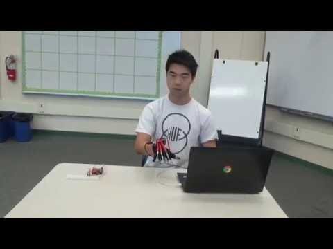
For my final milestone I assembled the robot, adding motors and mounting a robotic arm to a metal chassis. I was able to send signals from the flex sensors in the same way I did in milestone #2 except this time the signals moved the robotic arm. I was able to get the H-bridge connected and working fora while, but it burnt out before I could fully complete the project. I had a lot of problems with the H-bridge and spent most of my last few weeks researching about H-bridges and trying to figure out why my motors didn’t work with my H-bridge. I ended up trying 4 different H-bridges, but encountered different problems with each one. I also found that some of the input pins on my Arduino were broken which was what caused a lot of my problems. After changing pins I was able to get my H-bridge to work, however, the H-bridge ended up burning out on the final day so I was unable to put all the parts of my robot together.
Code:
https://docs.google.com/document/d/1l1SEHymp41PtzR-PTCdeNZBedU7bCwCumKuB50oT_Lo/edit?usp=sharing
For my second milestone I configured XBee using XCTU, then connected the XBees to two Arduinos which allowed me to wirelessly communicate between the Arduinos. I then sewed the flex sensors into my glove. I was able to turn on LEDs by sending commands from one Arduino to another using the XBees. I made each flex sensor correspond to a respective LED. My final project will not include LEDs, but I will use the same code to make the glove turn motors and control a ropotic armUsing the XBees was also challenging and took a few days. The biggest problem was learning how to write code that would work between the XBees simply because I had no experience coding with XBees and was still new to using Arduino. However, after a lot of research I was able to figure out how to use the XBees on Arduino.
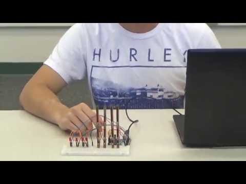
In my first milestone I set up the flex sensors with a breadboard. Each flex sensor contains variable resistors which change in resistance depending on the degree to which the sensors are bent. Each of the flex sensors is connected to a regular resistor as well which is used as a baseline to compare the resistor in the flex sensor with. I connected the sensors to Arduino to get the readings of the voltage passing through the sensors. This data essentially tells me whether or not the flex sensor is bent.. I then used code in Arduino to send a signal to four LED lights, each of which corresponds to one of the flex sensors, so whenever a sensor bends a light turns on. Later on I will use similar code to give specific commands to the robot whenever a certain flex sensor is bent. The biggest challenge was working with the breadboards because I was not familiar with how they worked. For example I spent many hours modifying my code and wiring to get the LED to light up. However, all I actually needed to do was connect the two separate sides of the breadboard Next I need to set up my Xbees with the Arduinos so that I can connect the various parts of the project.

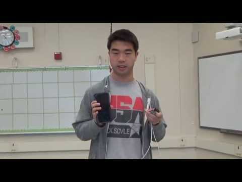
For my starter project I made a Minty Boost charger. It uses AA batteries to charge USB devices such as phones. By completing this project I got a lot of practice with soldering, and I learned about some basic electronic parts. The project uses resistors to prevent short circuits, capacitors to store electricity and make the current more smooth, inductors to convert the electricity from low to high voltage, and a diode to direct the current. I now have a much better understanding of how each of these parts work. My biggest challenge was soldering because before the project I had never soldered before. Some problems did come up, for example, I had to get a capacitor through a hole that I accidentally filled with solder. To do this I heated the solder that was blocking the hole then pushing the piece through.