Othello Game
A game of 6×6 Othello where one player is a human and the other is a computer.
Name
Kian N
Area of Interest
Electrical engineering and computer science
School
Urban School of San Francisco
Grade
Incoming senior
Reflection
Bill of Materials
| Part | Cost | Vendor | Documentation |
|---|---|---|---|
| Arduino AT Mega 2560 | $14.99 | Amazon | Arduino Mega 2560 |
| Adafruit 8×8 NeoPixel Matrix | $34.99 | Sparkfun | Adafruit NeoPixel Überguide |
| Sunfounder 16×2 LCD Display
+ Arduino to LCD I2C Backpack |
$9.99 | Amazon | LCD Guide |
| 7805 Voltage Regulator | $7.99 | Amazon | Sparkfun Datasheet |
| Slide Switch | $4.99 | Amazon | — |
Code and Libraries
- Time.h
- ArduinoSTL.h
- <algorithm>
- <vector>
- LiquidCrystal_I2C.h
- Wire.h
- Adafruit_NeoPixel.h
Important Notes
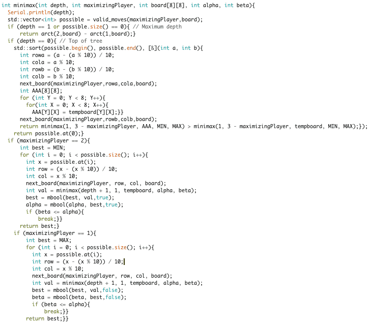
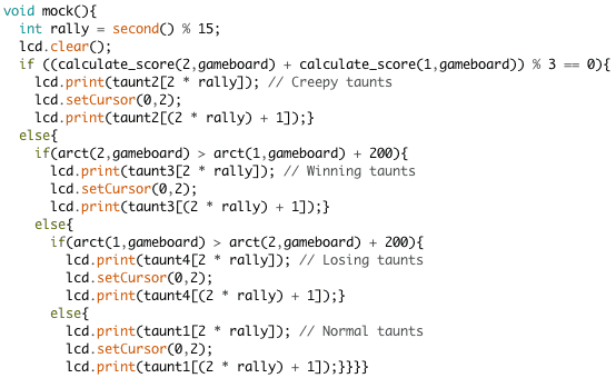
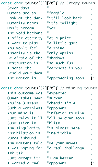
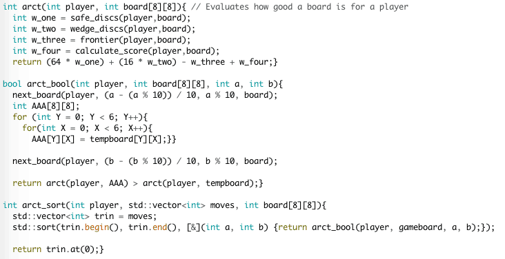
My fourth modification was to increase the quality of the moves made by the computer by having it look at future. The algorithm looks at all of the computer’s valid moves, all of the player’s valid moves should the computer make any given move, and calculates the arct score of the player minus the arct score of the computer. The player will naturally try to maximize its score, thus the computer will pick the best move with the smallest maximum value at the end of the game tree. I also programmed the LCD display to show taunting messages while the computer is calculating its move. Which taunt is displayed depends loosely on how long the game has been going on and how “good” the game board is for each player.
New Code

Demo


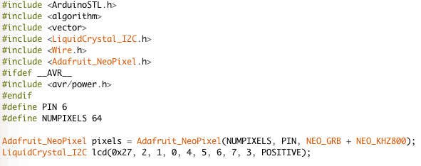
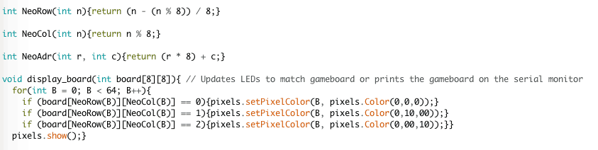
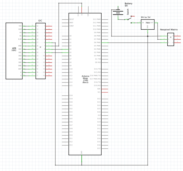
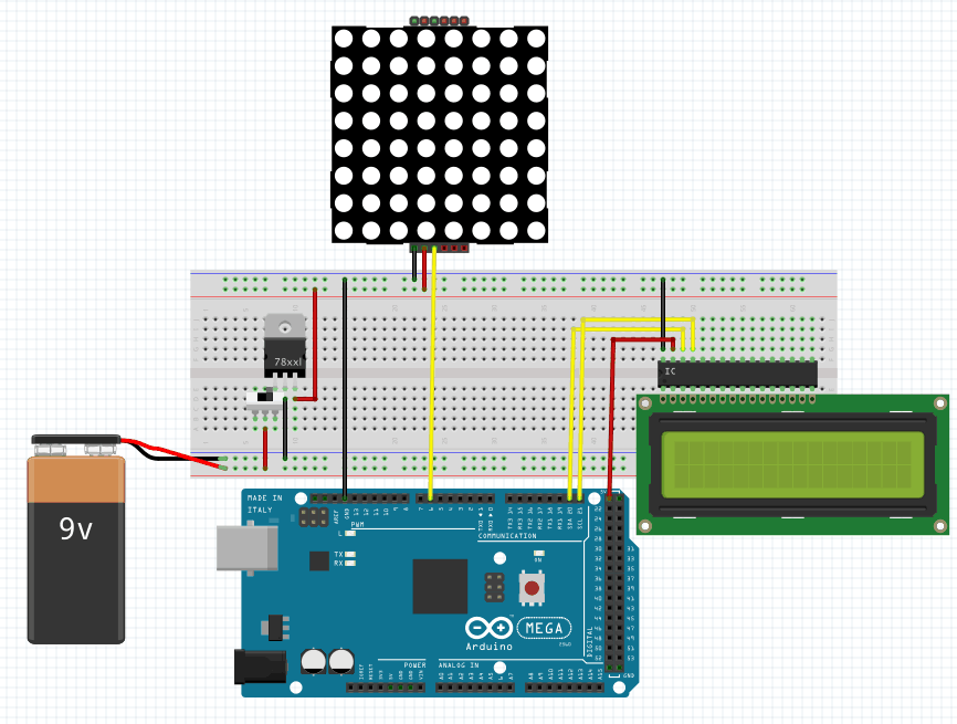
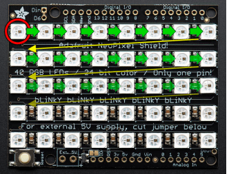
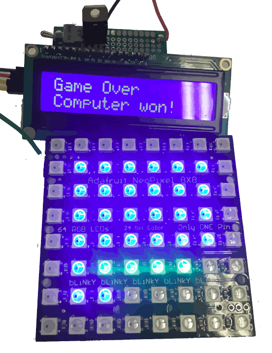
My third modification was to integrate an Adafruit Neopixel Matrix instead of the RGB LED matrix that I had previously been using. The new matrix uses a different hardware and software setup. Instead of using dozens of pins, the Neopixels only require power, ground, and one data pin. The Neopixels are linked up together in a progressive order so instead of addressing the matrix via rows and columns, coordinates in the code must be translated to an index from 0 to 63. The matrix is controlled with the library NeoPixel. An Arduino board does not put out enough current to light all 64 LEDs, so an external power source must be used. I used a 9V battery with a switch and a 5V voltage regulator. After integrating all of these steps, I soldered them to a perf board to reduce the number of wires involved. I also programmed the LCD display to show taunting messages while the computer is calculating its move. Which taunt is displayed depends loosely on how long the game has been going on and how “good” the game board is for each player.
New Code
New Circuit Diagram

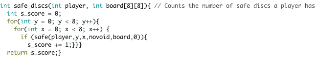
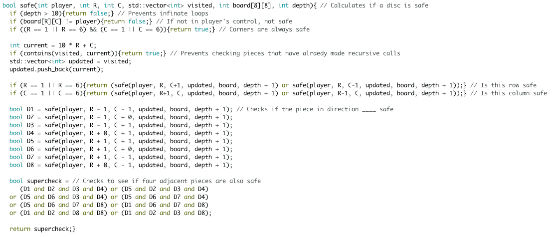
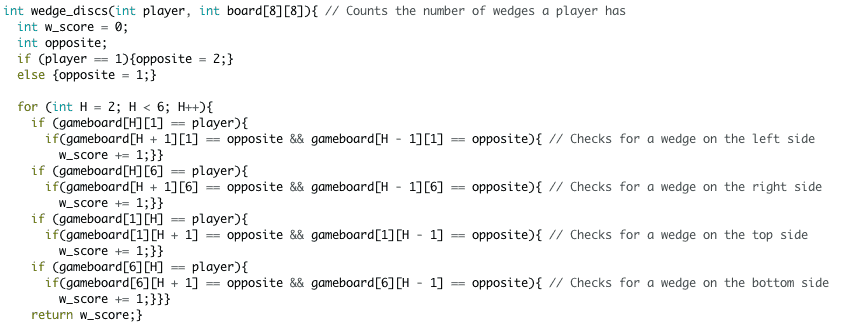
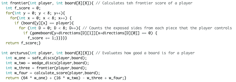
My second modification was to allow the computer player to make more intelligent moves, rather than randomly picking a valid moves. To do this, I had the Arduino sort all of the computer’s moves according to an evaluation function, called an arct score. The arct score has four features that determine how good a board is for a certain player: safe discs, wedge discs, frontier score, and raw score. I already created the functions that calculate these for Milestone 2, so some of the code for this modification can be found in older versions of the code, and the rest can be found in the code for modification 1. Safe discs, which have a weight of +64 each, are tiles that cannot be flipped once taken (ie, corners and pieces next to them). Wedge discs, which have a weight of +16 each, are pieces that, when placed, are already sandwiched on an edge between two pieces of the opposite color, thus making them almost impossible to take. The frontier score, which has a weight of -1, determines how exposed a player is by counting the number of empty tiles adjacent to tiles controlled by the player. The raw score simply counts how many tiles a player controls, and has a weight of +1.
New Code
Demo


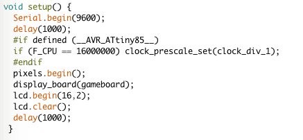
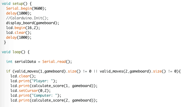
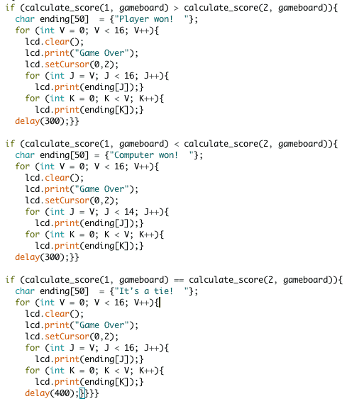
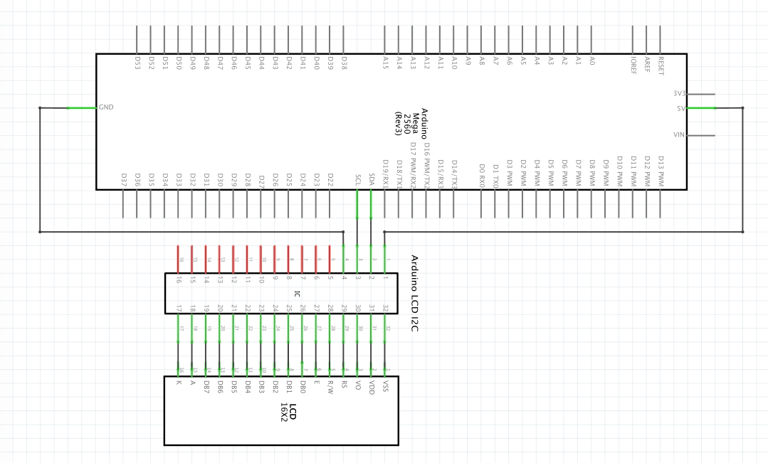
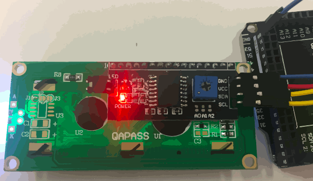
My first modification was to add an LCD display to tell the score and declare the winner. At this juncture, I replaced my Arduino Uno with an AT Mega 2560 due to the additional pins. However, the RGB matrix does not function with the AT Mega, so I will be replacing it with a NeoPixel matrix in a later modification, but until then I have removed the RGB matrix all together and displayed the gameboard on the serial monitor along with the player interface. The LCD Display is soldered to an I2C which communicates with the Arduino using only four pins: ground, 5 volt, and 2 analog pins. The code to interface with the I2C comes from the Arduino libraries Wire.h and LiquidCrystal_I2C.h. The scorekeeping functionality works by displaying the words “Player:” and “Computer” followed by the scores at that moment at the beginning of the void loop. The declaring a winner functionality is complicated by the addition of scrolling text. However, since the autoscroll function of the Liquid Crystal library did not suit my needs, I created my own scrolling text function by creating a string ending, which contained a message about who won, and had the void loop cycle through each letter, first displaying everything after the letter and then everything before the letter, to create a scrolling effect. Because I worked on this modification at the same time as the next one, the code for the following modification is the same code as the one linked below.
New Code

LCD Circuit Diagram

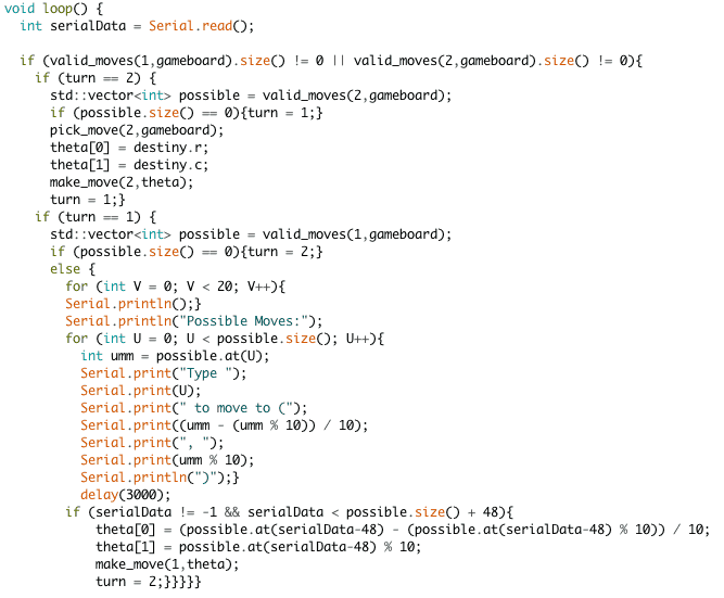
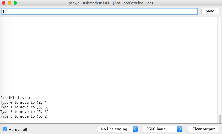
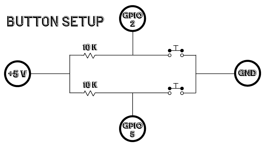
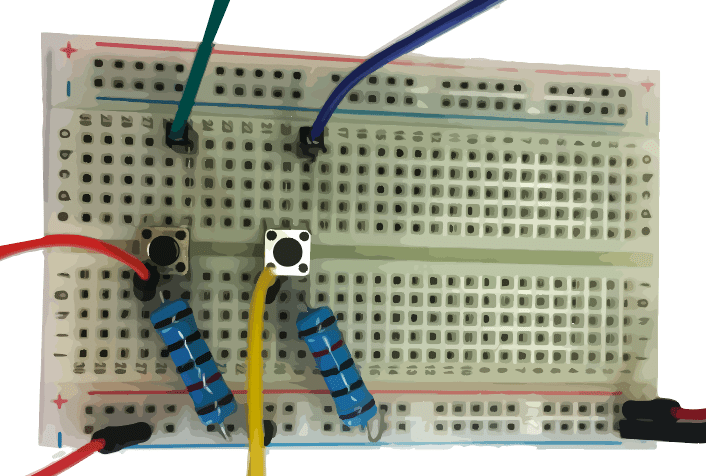
For my third milestone, I focused on adding a player interface to my Othello game. I Initially focused on adding buttons, one for toggling moves and one for selecting moves, but this did not work out for a variety of reasons. Since adding buttons would require me to use the 5V and ground pins, as well as 2 digital general purpose input output pins, all of which were filled by the RGB matrix, I had to create an interface between the shield and the Arduino using jumper wires and a breadboard. This layout was incredibly hard to work with, and the use of buttons led to a variety of hardware-centric problems. Ultimately, I came to the conclusion that using the serial monitor to type commands to the Arduino was more practical, so I pivoted the player interface to be software-centric as opposed to hardware-centric. Now, when it is green’s turn, the serial monitor prints all of green’s possible moves, along with a number corresponding to that move. When the Arduino detects that the player has typed something into the serial monitor, it translates whatever was typed into its ASCII number, checks to see if the number corresponds to an integer from 0 to the number of possible moves minus 1. If the ASCII does correspond to a valid number, the Arduino makes the move corresponding to the number.
New Code

Button Circuit Diagram

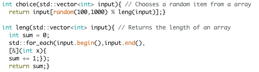
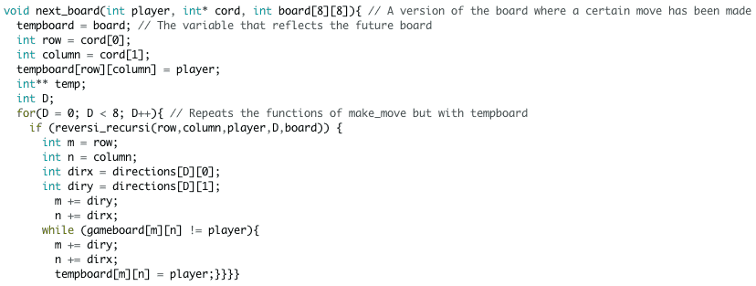
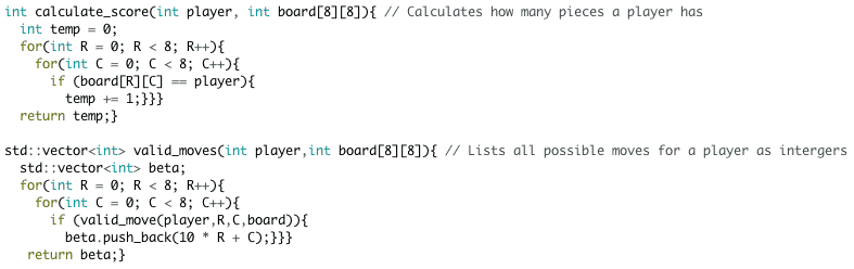
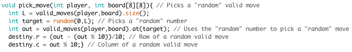
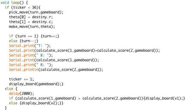
For my second milestone, I focused on a variety of coding and debugging goals with the end result of the Arduino making “random” moves and playing a full game of Othello against itself. The code written performed the following functions: picking a random number, producing an array representing the gameboard if a certain move were made, calculating a player’s score, listing all potential moves for a player, picking a random move, calculating if a certain piece was safe, a wedge, and how many frontiers it had. At the start of the game, the board is empty except for 2 red and 2 blue pieces in the middle. Then, a loop begins where, so long as the game is not over, blue makes a move, then red makes a move. When the game is over, the color of the winning player is flashed over the entire board. When a player makes a move, all of their possible moves are calculated and random number from 0 to the number of possible moves minus 1 is picked. The number picked is then translated into a move, and global variables are assigned the row and column values of the selected move. The program then uses the code from milestone 1 to make the selected move and flip any sandwiched pieces. The other functions I created for this milestone will eventually be used to allow the Arduino to make more intelligent moves.
New Code
Demo


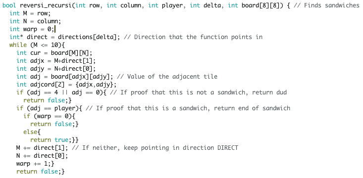
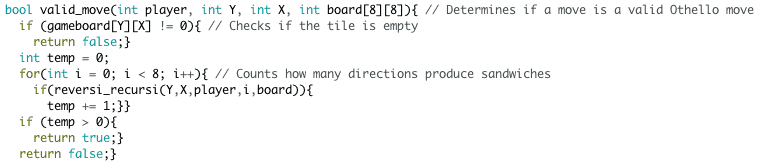
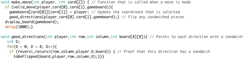
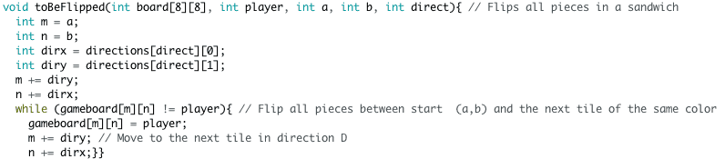
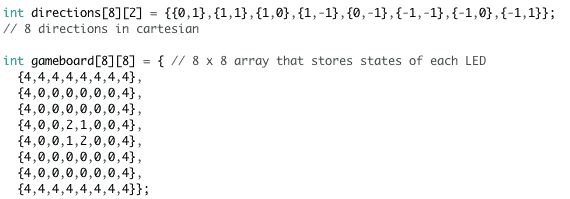
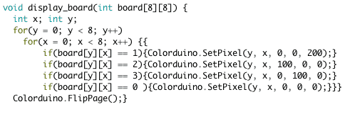
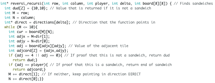
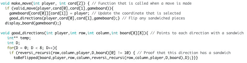
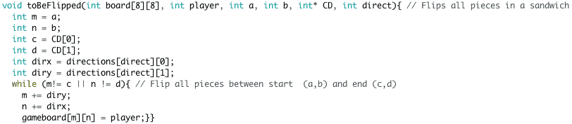
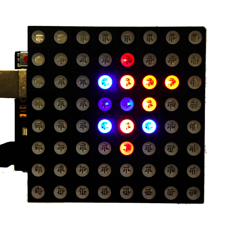
The first step in making my Othello game was to create a board where you could make valid Othello moves, meaning that I can only make a move if it creates a sandwich and any pieces caught in that sandwich will be flipped from the opposite color to my color. I did this by integrating an Arduino board with an 8×8 RGB LED matrix, even though I will only be using 36 out of 64 cells in the grid. I then used the Arduino library Colorduino as the basis for my c++ code. The grid operates from an 8×8 array of integers called the game board, where player one (blue) is represented by 1s, player two (red) is represented by 2s, empty spaces are represented by 0s, and the outer rim cells are represented by 4s. The arduino file routinely runs a function called display board that takes the latest version of the game board and changes LEDs accordingly. Whenever a move is made, the arduino checks to see if a move is valid, and if so changes the color of that LED, along with any LEDs that are sandwiched between the move and any pieces of the same color. Both valid move checker and the function that flips sandwiched pieces operate using the same function that detects sandwiches: reversi recursi. Reversi recursi starts in a certain cell pointing in one of 8 directions and keeps moving in that direction until it determines that it has found a valid sandwich or can prove that the move is invalid. If the move is valid, then it returns the coordinate of the other end of the sandwich. If the move is invalid, it returns a dud value. The valid move function checks to see if reversi recursi returns the dud or not. The flipping pieces function points in the same directions that produced sandwiches and flips everything in that direction until it hits the coordinate returned by reversi recursi.
New Code
Othello Rules


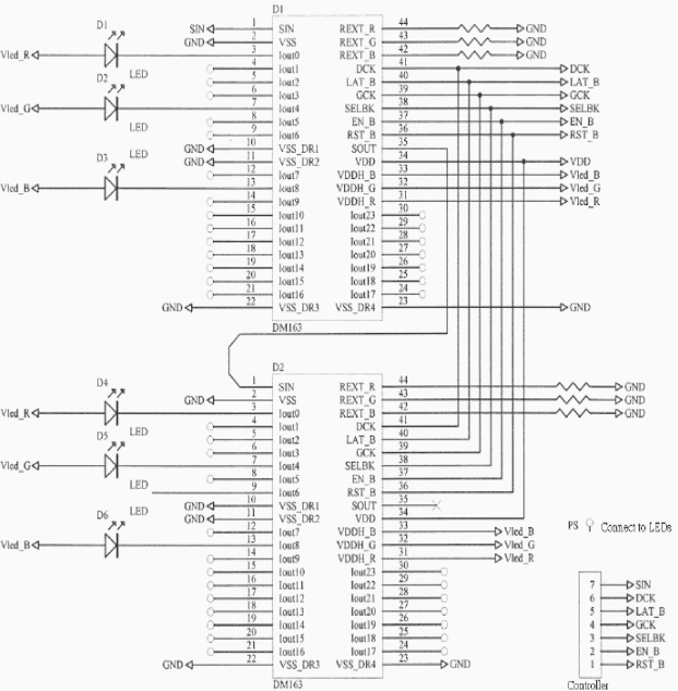
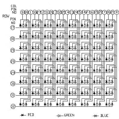
RGB Matrix Circuit Diagram
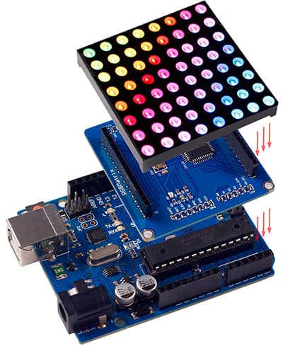
- Diagram of interaction between RGB Matrix, driver shield, and Arduino. Photo from http://wiki.sunfounder.cc/index.php?title=File:RGBMATRIX1.jpg
- Diagram of RGB matrix driver shield Application Diagram. Photo from http://wiki.sunfounder.cc/images/4/44/DM163_datasheet.pdf
- Diagram of LED matrix from http://wiki.sunfounder.cc/index.php?title=RGB_Dot_Matrix_Explanation
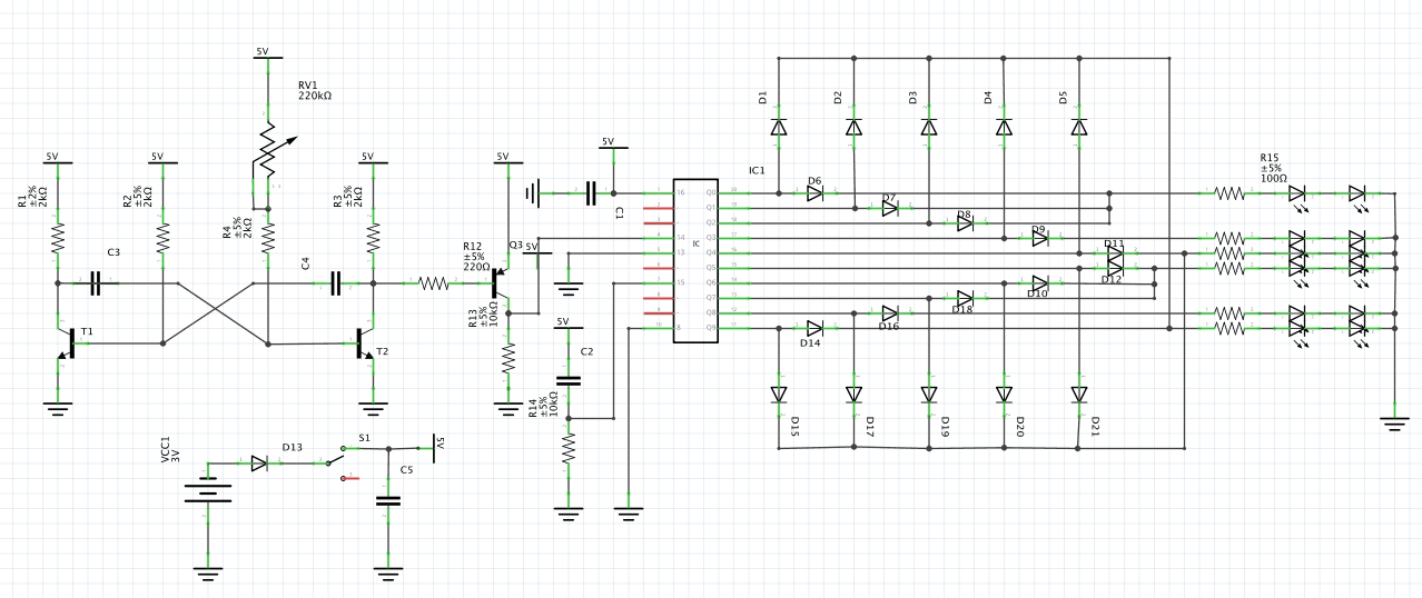
My starter project is the led traffic stoplight. It includes 14 resistors, 21 diodes, 12 LEDs, a trimmer resistor (aka a potentiometer), 3 transistors, an IC, 3 electrolytic capacitors, and 2 ceramic capacitors. When the switch is closed, power goes from the battery into the first section of the circuit: a collection of resistors and transistors regulate the power input to the integrated circuit. The resistors in this section prevent any other components from being burned out from excessive current. The transistors in this section act as switches; when power enters the base side, the electric current from the one end is boosted and ejected out of the third side. The electrolytic capacitors, which store more charge than the ceramic ones, store electric charge. The ceramic capacitors regulate the power going into the IC from a different set of inputs. This section of the circuit also includes a potentiometer (a resistor with a knob that alters the resistance) which regulates the speed of the traffic light. The integrated circuit contains a set of smaller electronic components that control when each led turns on. The many outputs of the IC are then regulated by many diodes which act as one-way gates for current to prevent the current from flowing in places that it should not. Afterwards, several more resistors reduce the current until it is an amount that the LEDs can handle. Finally, the current, regulated by the diodes and IC, turn on in a stoplight-like fashion. The LEDs periodically go from green to yellow to red, with each dimension showing the opposite color of the other to prevent accidents. There is also a lag between a light turning red in one direction and a light turning green in another to prevent collisions. However, the red LEDs in the direction perpendicular to the circuit board do not work due to a broken copper ring in the circuit board, but since they are in parallel with the other LEDs, the rest of the circuit is unaffected.

Circuit Diagram
Close Up

Comments
Nice job, Kian! Impressive!