")
Hi, my name is Kevin, and I am a rising Junior at the Columbia Secondary School for math, science, and engineering.
Problems Fixed Update – After looking through another Bluestamp students code for this project, I realized that they were not using the default pin numbers to connect the ps2 wireless dongle to the arduino uno. I learned from BSE student Indigo from San Francisco that the default 13-10 pin numbers do not allow for proper communication between the arduino and the PS2 controller because pins 8, 11, 12, and 13 do not work on the motor shield. I tried the change and now all buttons work on the remote.
My main project is an RC Tank controlled by a PS2 controller which was a project designed by Paul Bleisch (http://paulbleisch.com/blog/2013/01/03/simple-remote-controlled-arduino-tank/). The way it works is that an arduino is connected to a motor shield which is then connected to the PS2 controller receiver. It is powered by a portable phone battery pack which provides 5V. The motors are connected to a 58:1 GR gear box setup as a compound gear box which means that for 1 full rotation of the motor, 58 rotations will be outputted from the gearbox. This configuration compensates for the 5V battery. The output of the gearbox is connected to multiple sprockets and wheels which are on a track similar to a real tank. The receiver is connected to the arduino through about 6 wires that deliver both power and data. The motors are connected to a motorshield for the arduino created by adafruit. The motorshield has a big tolerance for changes. It can use independent power instead of using the arduino’s usb power; anywhere from 5V to 12V can be used to power your motors. You can use up to 4 DC motors and 2 servos. It can tolerate up to a peak current of 3A. The motorshield uses an H-bridge to control the direction of the motor by controlling the current flow. It does not allow the current to destroy the arduino when it makes the motors spin backwards. There were many challenges that I encountered in building this robot. I used 4 sprockets instead of 2 so I had to modify one of the axles to fit the sprocket as well as line up with the other wheels and sprocket. I also had problems while making the controller control the arduino. I figured out that the problem was a faulty receiver and errors in my code. I used a new controller and after that the communication between the receiver and the PS2 controller was resolved. The problem then became that the PS2 controller button presses were not being detected. If you held the button it would sometimes detect it as a single button press or sometimes not at all so the motor would not spin much if at all. This was something that was able to be resolved in the code. The current problem with my tank is that the remote only works intermittently. The remote will sometimes make the robot move and other times it wont. This is due to the code which I have not been able to completely fix. Once this problem is resolved it should in theory work without problems. I have learned with this project as well as with my starter project how to properly use a hacksaw and solder. I also learned how to use different libraries since I had to use 2 different libraries in my arduino code and make them work together. I used the example code for the PS2X library and motorshield library to aid the creation of the code. I mostly used the example code to learn how it worked especially since I had to combine both libraries. I also learned how to more easily debug my code by commenting things out and just leaving the bare minimums and using the serial monitor. There are many improvements as well as many modifications that can be made to the project to make it better.
My time at Bluestamp Engineering was a great experience as a passionate engineering student who was looking to get new skills while not having to sit in a classroom and being able to apply those skills. Coming in to the program I did not know exactly the layout of my day and what it would be like but after the first day I realized it was the place for me. I was quickly able to get started in my project after practicing my soldering and learning the safety protocols. I worked mostly independently during the first couple of days but soon I began to reach out to the instructors for help when I needed it and remembered that I was in a room surrounded by other engineers just as passionate as I was who I could reach out to. I became so engaged in my project I did not take my break one day and the instructors allowed me to do so which was great for me. I could get to work as soon as I entered the building and was only interrupted when it was time for a lecture/time to go. Even though it was not extensive I did meet a lot of new people and got to see the ability of others. I was able to learn concepts through the lectures taught by the instructors who were currently becoming engineers. They shared their experiences and things they have learned with us. I was able to finish my project and fix small bugs on my own time. Any questions I had or anything I needed help with, I was helped with after attempting it on my own which I liked because it forced me to try and resolve it myself before getting help. I was also able to see how they worked together to solve problems they were not sure about. One of my problems was worked on by about 3 of the instructors including one of the co-founders, Dave, who walked around the room keeping in touch with all the students. I would recommend this program to any student who has or think they could have a passion for engineering. This program will make you feel confident and give you the boost you need to continue to pursue engineering.
Bill of Materials- https://docs.google.com/a/columbiasecondary.org/spreadsheets/d/1UVRTaxtt22I7wRBtyLy2osMvas8ZcZ0zQSOXTlSnZ8Q/edit?usp=sharing
Schematic –

Code – RC_Tank Code
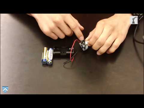
My starter project is a minty boost charger. It is a small device that uses 2 AA batteries to charge any mobile device. The way it works is that it converts the 3 volts from the AA batteries to the 5 volts required to charge your phone using an LT1302 chip. The current from the 2 AA batteries is first stored in an inductor. That current has 2 paths to go to which is controlled with an NPN transistor integrated in the IC. Those two paths are to the negative end of the battery or towards a diode which has a capacitor in series with it. The current is stored in the inductor temporarily in the form of a magnetic field. When the switch is connected to the negative side of the battery, the current shorts to the ground. However, when the diode path is selected, the current only goes in one direction to eventually get stored inside a capacitor. The voltage that is stored is now 5v due to the time it spent in the inductor. You can not let the switch stay closed for too long because eventually the current will be released from the inductor since the storage is temporary and it will short because its flowing towards the negative terminal. From here it goes through the USB into your device. The other capacitors in your circuit are used to make the waves square again because when the current is released from the inductor, it is released over time causing the wave to become rounded. The voltage output is controlled through an integrated function of the IC called a feedback circuit which is controlled by the resistance of the resistors.