Glove Controlled Robotic Arm
A robotic hand controlled from a distance is capable of completing many jobs: even in environments hazardous to humans.
School
Monta Vista High School
Grade
Rising Junior
Overall Reflection
I had fun constructing this project, as I was able to learn the basics of both electrical and software engineering. My experience in coding will especially help me in the future, as coding has become a fundamental part of almost every field of engineering. All of the resources, whether it was from the internet or from the instructors, were helpful and essential factors for my project. The environment of Blue Stamp was also a fun and supportive place to work on my project, as I was able to learn may concepts of engineering while also making new friends. Overall this program was a really great experience for me.
Final Milestone
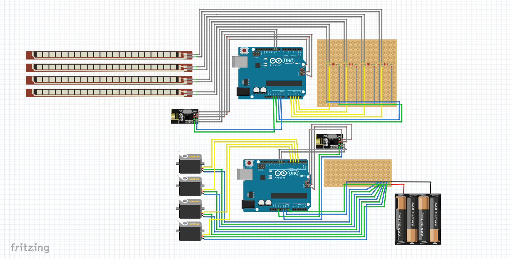
Similar to my second milestone, each flex sensor controls different servo motors through the bending of the sensors. However, instead of sending analog values directly to the digital pins on the Arduino, the data first goes to a nrf24l01. There are two nrf modules in the project: one transmitter and one receiver. The analog values are sent to the transmitter nrf module, which then sends the data through radio waves to the receiver nrf module. The receiver nrf module then sends the data to a separate Arduino to control the arm.
A key component of this milestone is the nrf module. The nrf modules can be coded as either a transmitter and a receiver. They use the 2.4GHz band and can operate with baud rates from 250kbps up to 2Mbps. There are also eight pins on this module. Two of the pins, Vin and GND, are what powers the module. The CE and CSN pins are wired to the digital pins of the Arduino and can set the modules in standby or active mode. The three SPI pins are wired to the ICSP pins of the Arduino and are in charge of communication. The last pin, the interrupt pin, is not used in this circuit. A major problem I faced while working on this milestone was having the nrf modules interact with each other. In the beginning, I tried to have them send simple messages, but nothing showed up on the serial monitor for the receiver code even though the serial monitor for the transmitter displayed that data was being sent. After research and rewiring the SPI pins to the ICSP pins instead of digital pins, I was successful in having the two nrfs interact. A modification I have in plan are to replace the Arduino UNO on the glove to an Arduino NANO to make the circuit on the glove smaller. I also plan to add a battery pack for the glove so that the glove does not have to be connected to my computer.
Second Milestone
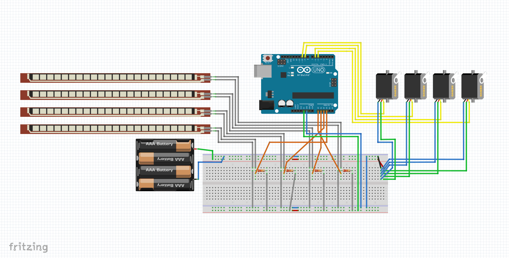
By wearing the glove and bending their thumb, index finger, middle finger, and ring finger, the robotic arm can be controlled. Each finger controls a different axis of the arm: the rotation, main actuation, second actuation, and the gripper. A key component of this milestone is the flex sensors. Flex sensors have polymer ink with conductive particles inside that causes a certain resistance to the current. When the sensor is bent, the distance between the particles increases, also increasing the resistance. These flex sensors, along with the 22kOhm resistors on the breadboard, create a voltage divider. A voltage divider works by using two resistors in a series to divide the input voltage and creating a different output voltage. When the flex sensor is bent, the resistance increases, increasing the voltage drop of the flex sensor and therefore decreasing the output voltage. The analog pins in the circuit read the changes in the voltage and send them to the Arduino, where the uploaded code converts these values to angles of rotation for the servo motors, allowing the arm to function. A major problem I faced while progressing in this milestone was having a single servo motor function with a single flex sensor. After learning many concepts, I was able to figure out through the serial monitor that the flex sensor was successfully causing differences in values, but that the servo motor was physically broken. After replacing all the servo motors I was able to control the servo motors with the movement of the flex sensors.
First Milestone
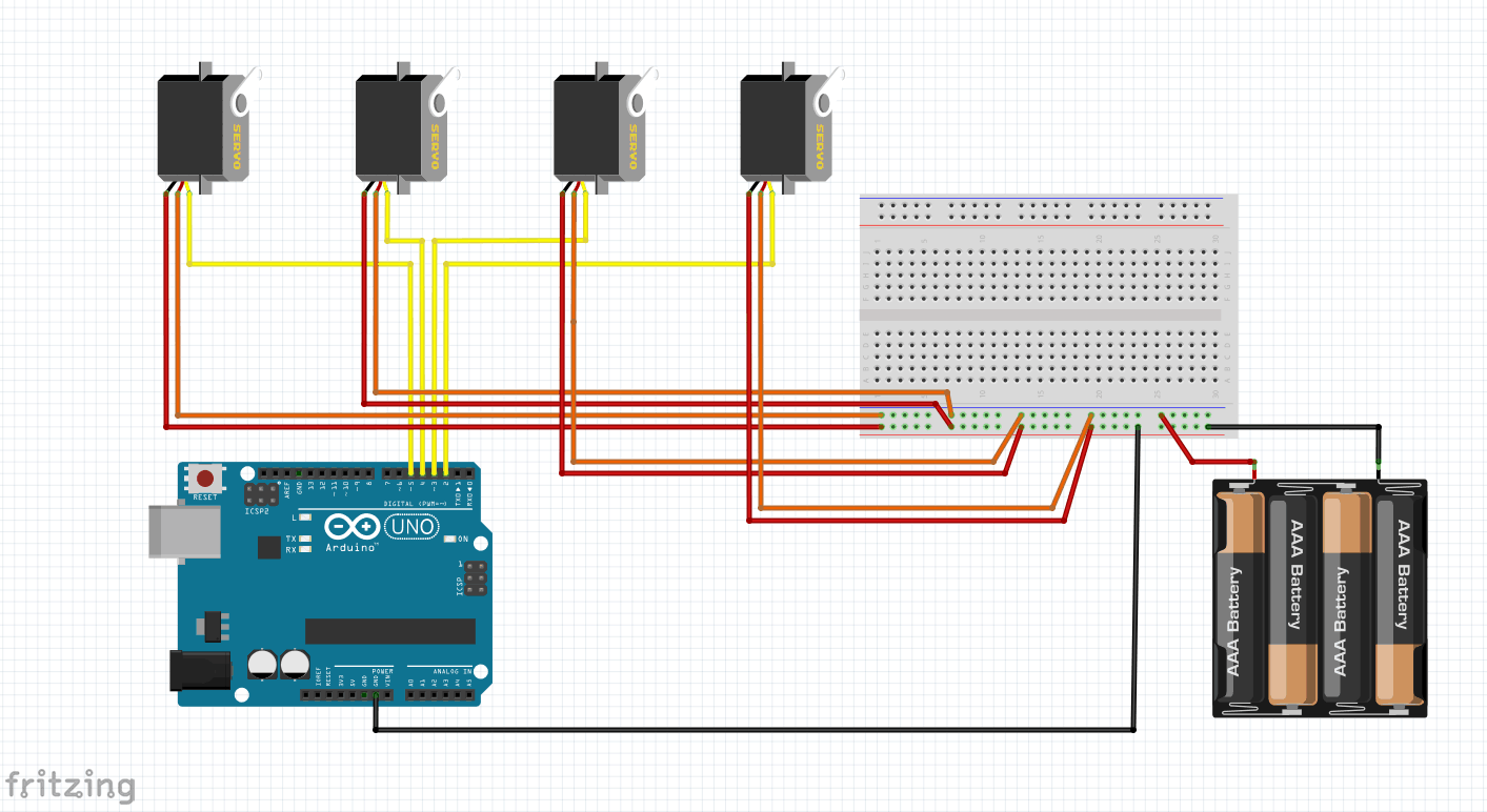
The robotic arm functions when any changes are made to the numbers on the controller and the data is sent to the Arduino. The yellow pins of the 3pin servo motors are wired to the Arduino to receive the signals, while the other red and orange pins are wired to a breadboard to receive energy from a 6V battery pack. This battery pack is required for the arm to function because my computer is not enough to power the four servos for function.
Key components include the servo motor, which is able to rotate a certain amount of degrees because these servos send a Pulse Width Modulation through the control wires, such as the minimum and maximum pulses, allowing the rotor to spin to the desired position. Other components include the breadboard, which sends current from the battery pack to the servos, and the Arduino, which is able to store the code for the software to control the servos. An example of the code is
if (Serial.available() ) {
servo1Pos = Serial.parseInt();
servo2Pos = Serial.parseInt();
servo3Pos = Serial.parseInt();
servo4Pos = Serial.parseInt();
These lines of code allow each servo motor to obtain the servo position values from the serial ports. A major problem I faced while working on this first milestone is that whenever I moved the arm, the arm would start to shake very wildly and would not stop. Through research, I found out that this was caused by a fault in the way the Arduino sends pulses. After trial and error, I was able to greatly reduce the shaking by placing a cable tie around one of the servos.
servo1Pos = Serial.parseInt();
servo2Pos = Serial.parseInt();
servo3Pos = Serial.parseInt();
servo4Pos = Serial.parseInt();