RC Tank
My project is the creation of the RC Tank number 212 with a twist. The tank will not have traditional treads, but rather it has two large drive wheels and a caster ball for balance.
Engineer
Kaan S.
Area of Interest
Software and Design Engineering
School
Los Gatos High School
Grade
Incoming Junior
Reflection:
Bill of Materials
Final Milestone: Full Assembly
For my final milestone, I needed to assemble the body of the tank. This step seemed pretty straight forward but, I ran into a bit of trouble. I wired in a lightweight yet powerful battery that would be able to fit on the body of the tank properly. I wired in a solid switch that turns on or off the power coming from the battery. The battery is physically mounted on the gearbox and motor assembly so the motors could move the weight of the battery instead of dragging the battery on the caster-balls. The Arduino and motor-shield, being the lightest component group, is mounted closest to the caster-balls. With this layout, the wheels get enough weight on them to grip the ground and be able to move at the speeds that I prefer. I used a zip ties to clean up the wiring and secure the placement of the battery.
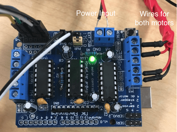
Second Milestone: Motor Control
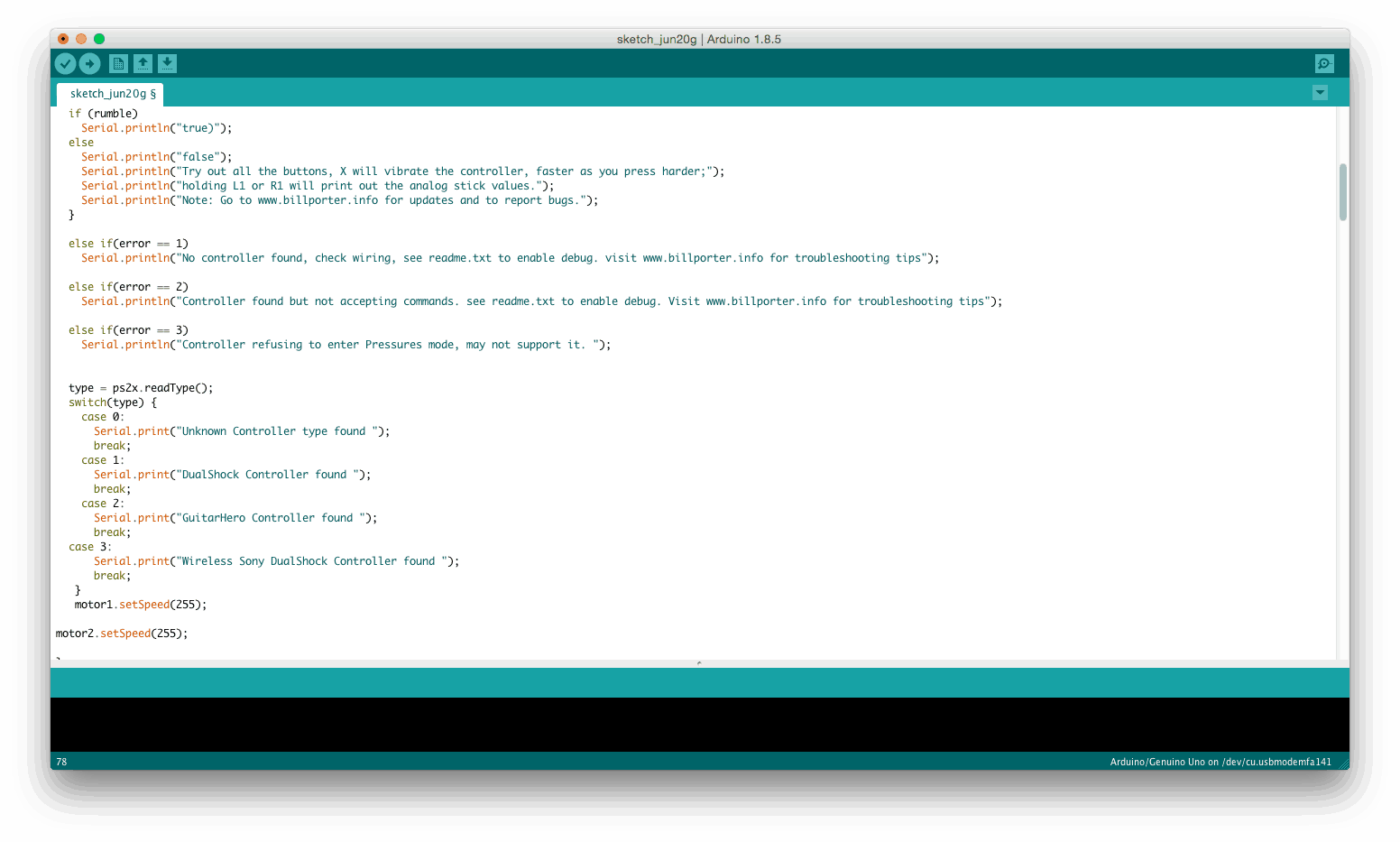
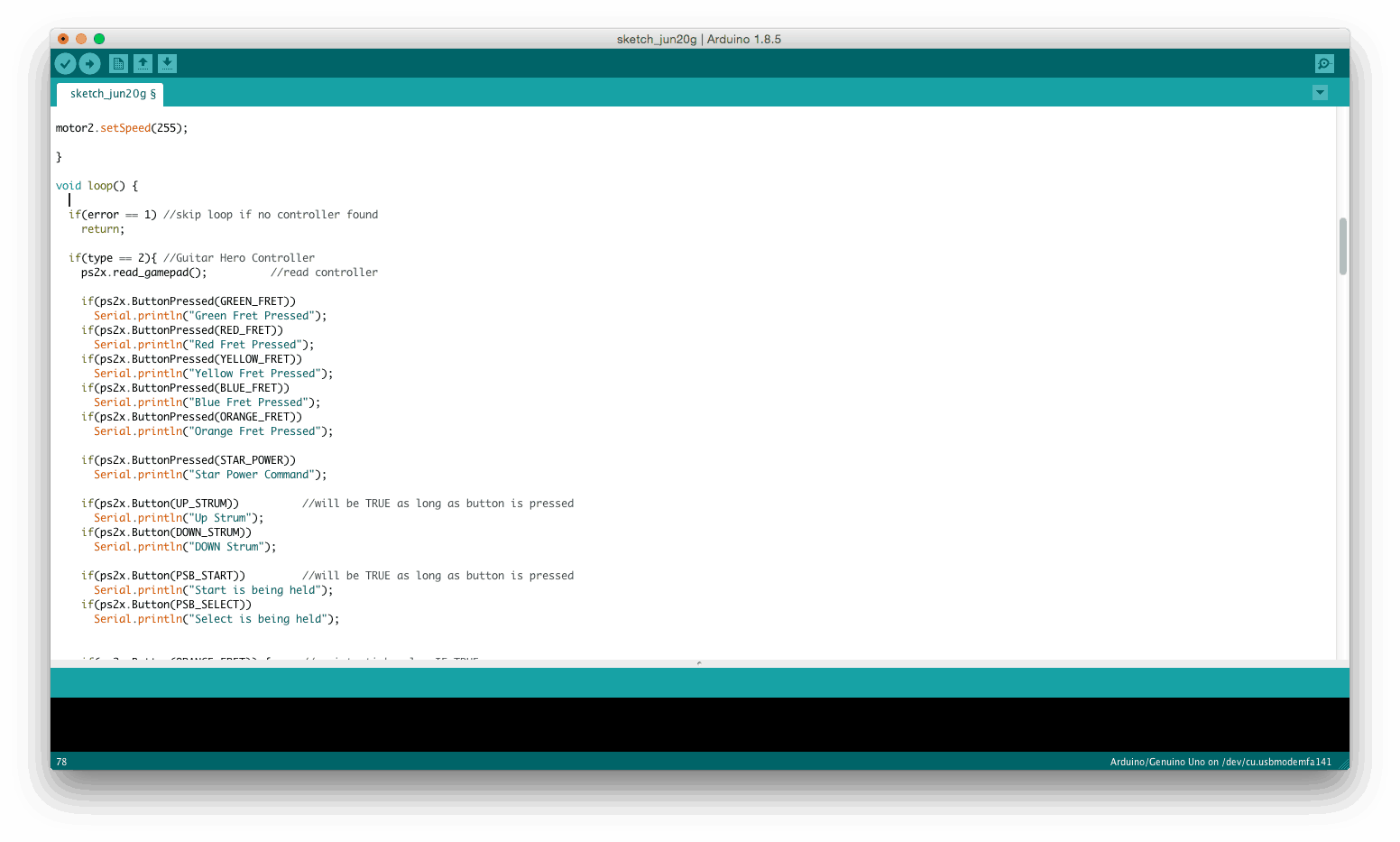
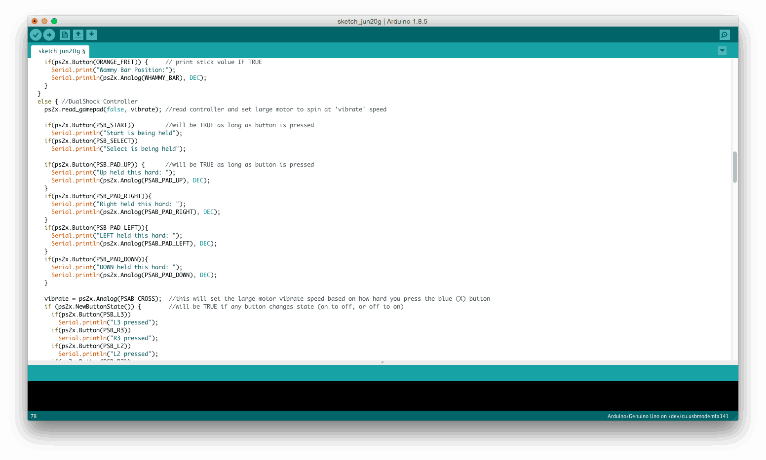
My second milestone is to connect the motors to the motor-shield and get the motors to move according to the input of the PS2 remote. Wiring the motors to the shield is pretty straight forward, but there was a few problems cause by the other steps. To get the motor shield to output power appropriately I needed to download another library for the Arduino to understand how to use the motor shield. With the motors in place and the Arduino wired up, all I have to do is to merge all of my coding to have the remote function with the motors. After writing the correct code, I was able to get the motors moving from the remote in each direction. My next milestone would be to situate off of my components onto a base and wire in an on/off switch so I do not have to mess with wires each time.
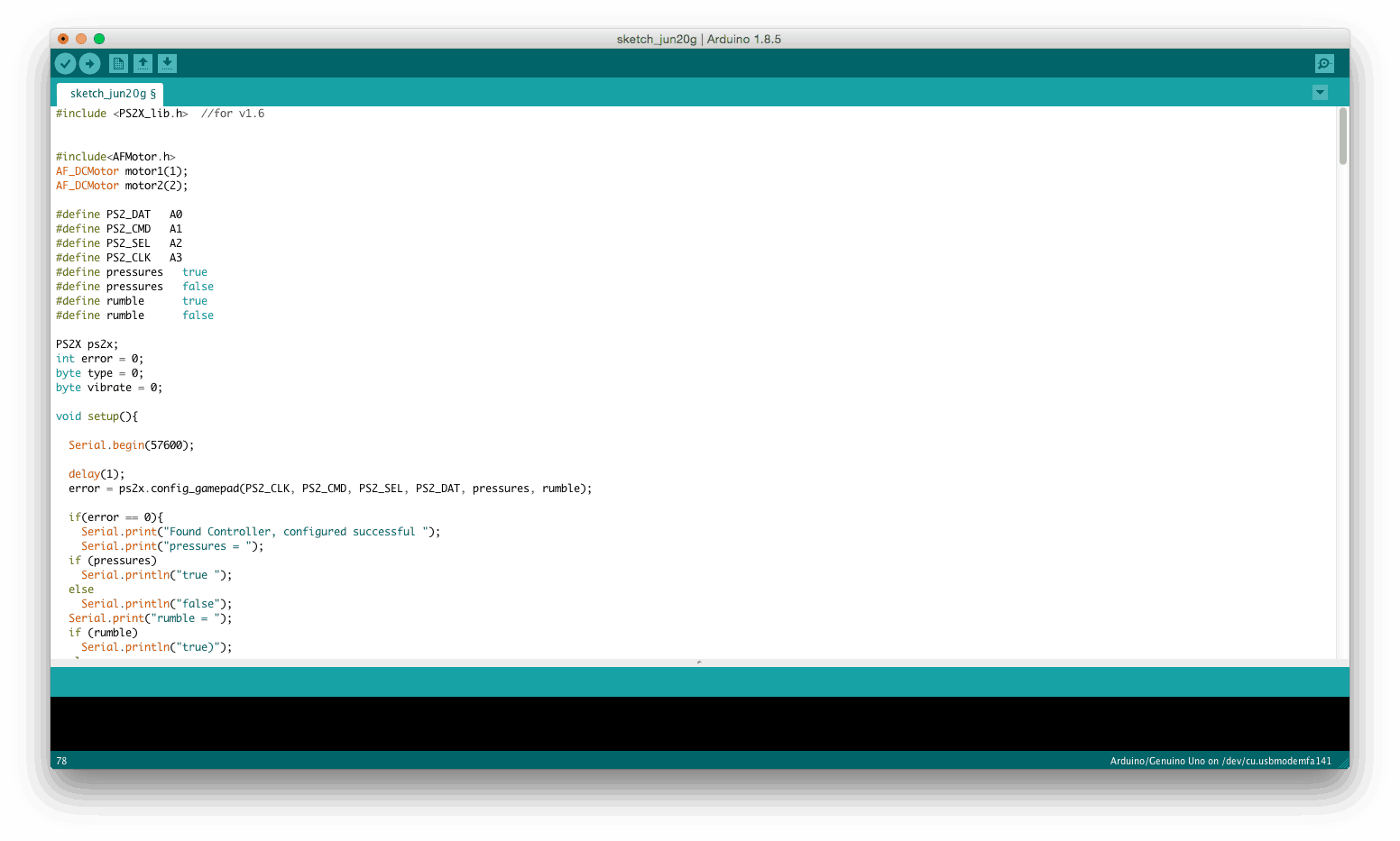
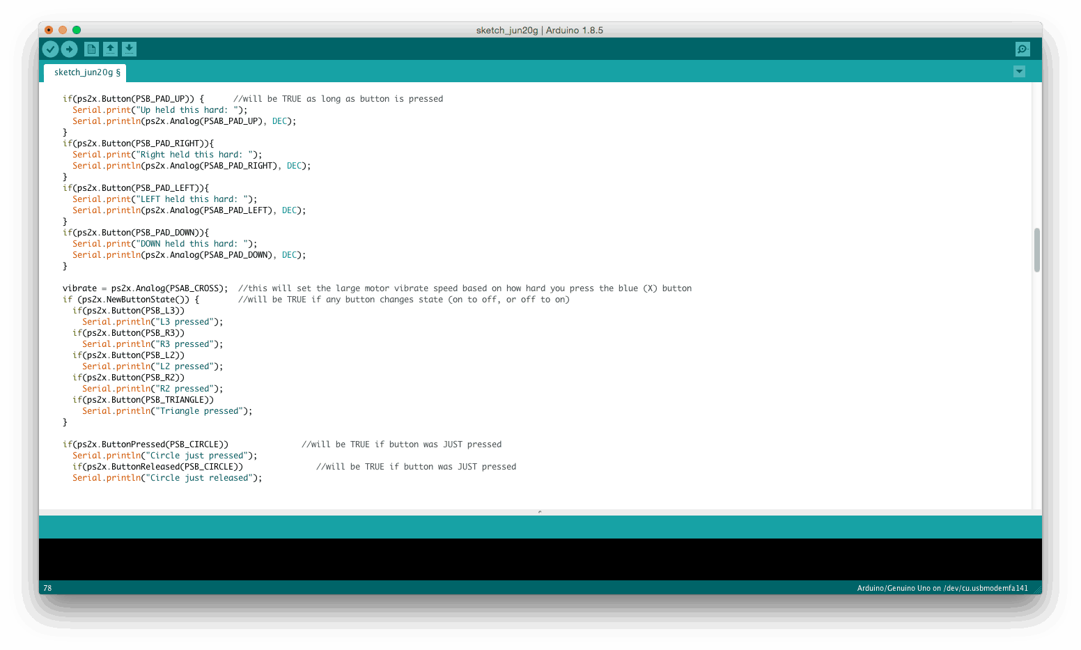
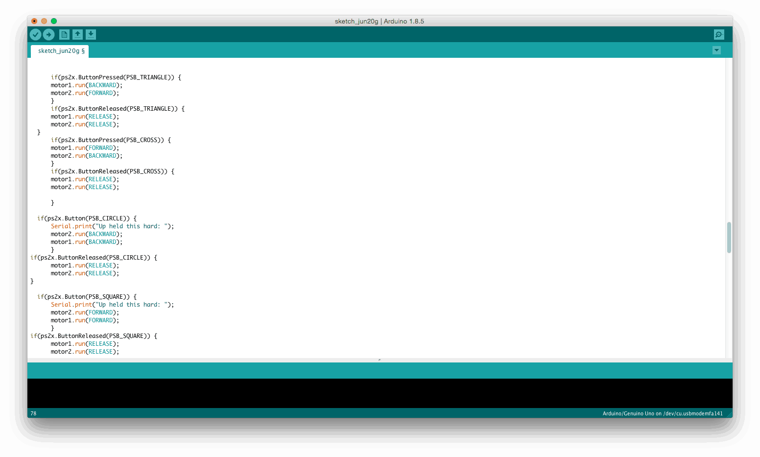
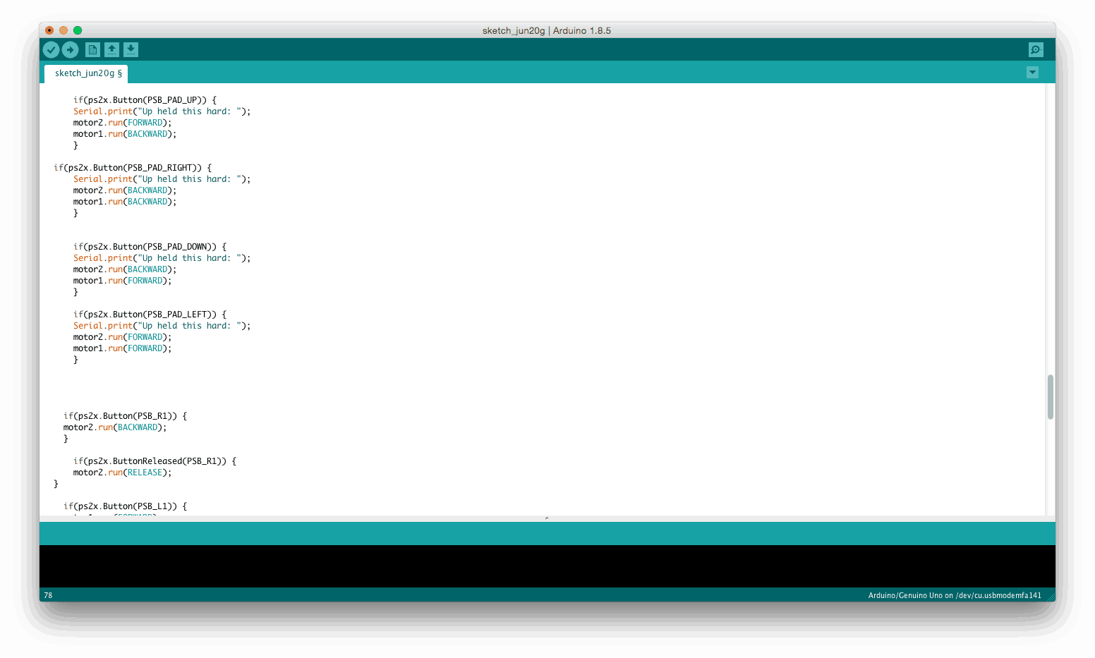
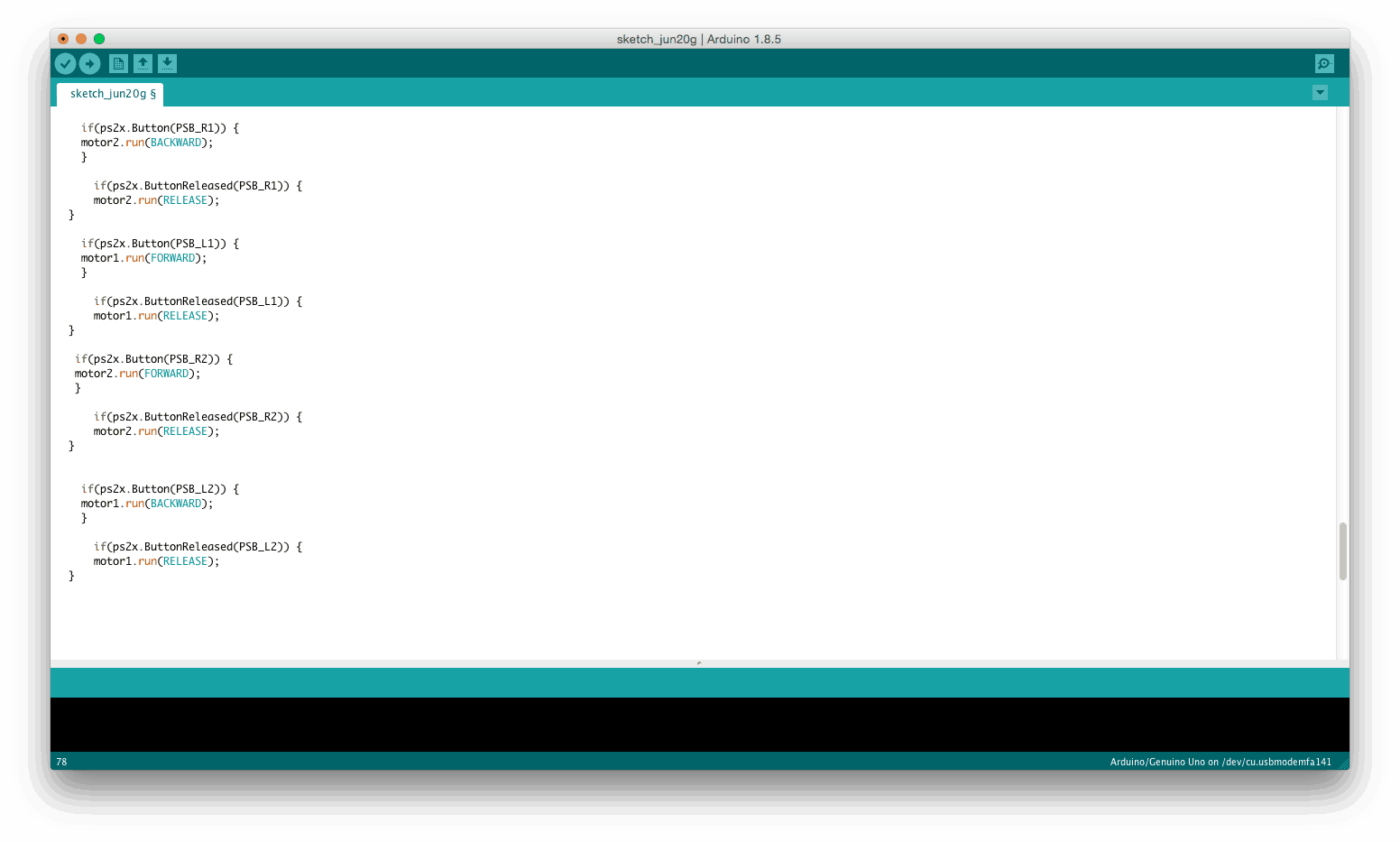
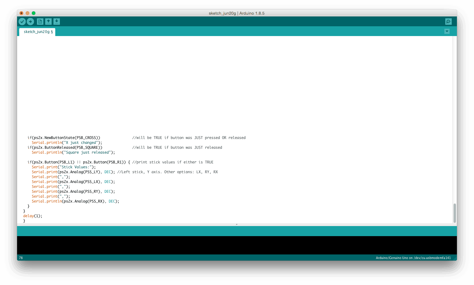
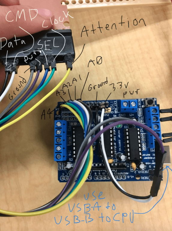
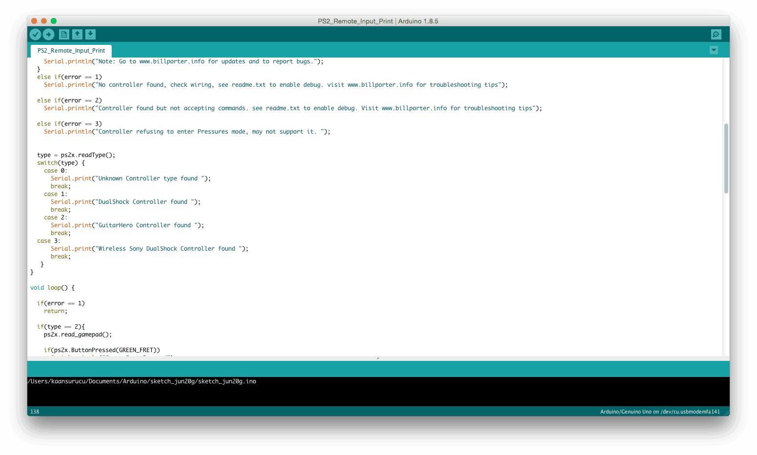
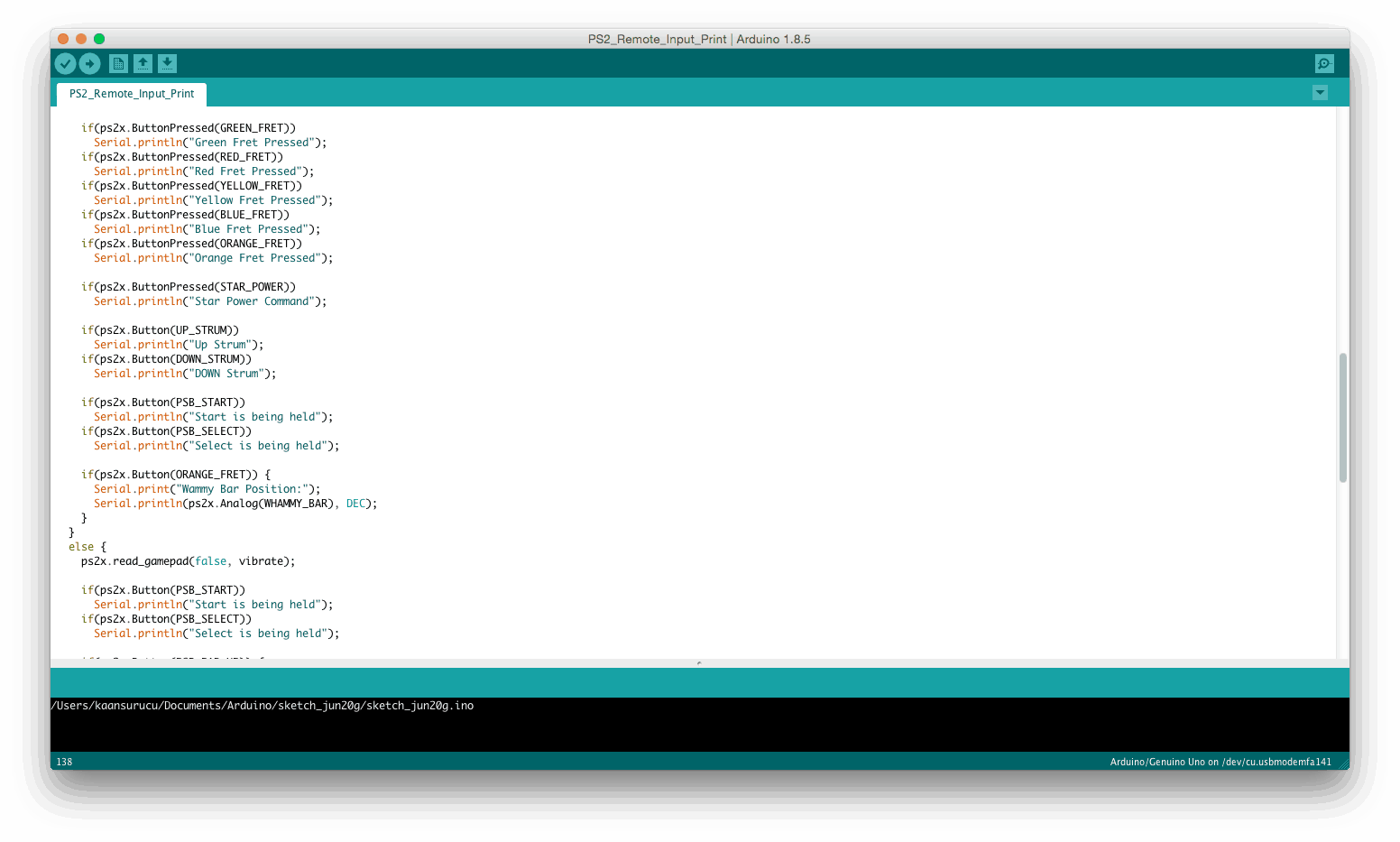
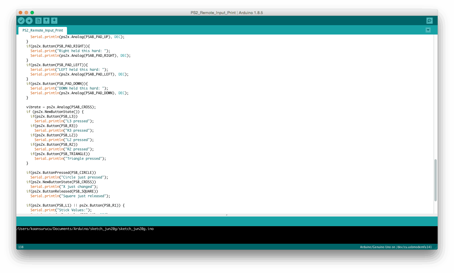
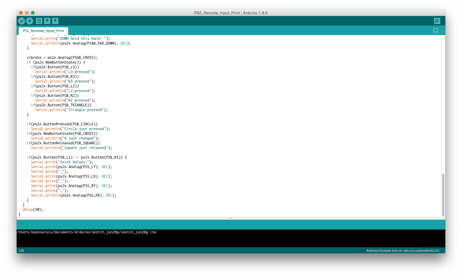
Full Motor Movement Code and New Wiring Diagram
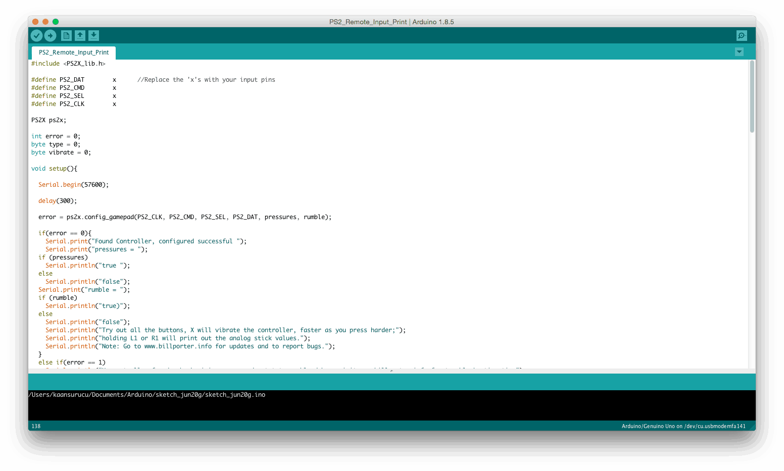
First Milestone: Remote Connection
My first milestone was to figure out the wiring for the PS2 remotes receiver to the Arduino’s motor shield. I encountered a few problems on the way. First of all, getting the wire of the receiver plugged into an input on the motor shield was a bit tricky. The problem was that where was no input on the motor shield so I needed to solder in female pin connections into my motor shield. Once the wiring was handled, I needed to learn the code for the remote and download the library to get the PS2 to be able to have the receiver communicate with the Arduino. There were multiple different libraries depending on the Arduino, motor shield and the PS2 remote. I ended up downloading 2 libraries, one for the receiver to communicate with Arduino and one for the Arduino to work with the motor shield. Once the wiring was complete I used a simple print function to verify that the remote and receiver work. Finally, I needed to connect the remote to the receiver and run the print code. This last step too a bit of tinkering to be able to get connected with ease, but after a bit of adjusting the pins and the code I got it to work properly.