Wall-E Robot
My project is an emotive, Wall-E-esq robot. It’s cute, it’s creepy, and it doesn’t do much. It’s eye opening and endearing. It’s everything you want your first robot to be.
Engineer
Joshua
Area of Interest
Electrical Engineering
School
SAR High School
Grade
Incoming Senior
Reflection
During my time at Bluestamp, in addition to building my robot, I created a strong foundation for my future engineering endeavours. The first few things a learned were important physical skills that all engineers must have under their belt before they can start any sort of robotics project. How to solder, dremel, drill, and saw components for my project. As my project progressed I had to learn more advanced skills. Things like how to code, understanding arduino logic, and proper troubleshooting techniques. I am very satisfied with my acquisition of these skills to my toolbox. Although I wasn’t able to add a few ideas to my robot in the allotted time, I am confident I can see work through on my own, adding whatever components I so desire. I plan on taking the things I learned this summer and integrating them with previous interests of mine such as art and design. Taking my new outlook and understanding for electronics straight into my college studies
Final Milestone
#include
#include #include
UltraSonicDistanceSensor distanceSensor(7, 8); // Initialize sensor that uses digital pins 13 and 12.
#include
#include
#include “Adafruit_LEDBackpack.h”
Adafruit_8x16minimatrix matrix = Adafruit_8x16minimatrix();
LiquidCrystal_I2C lcd(0x3F, 2, 1, 0, 4, 5, 6, 7, 3, POSITIVE) ;
// Pins
int x = 0;
bool state = false;
unsigned long t1;
unsigned long t2;
unsigned long pulse_width;
float cm;
float inches;
// Anything over 400 cm (23200 us pulse) is “out of range”
const unsigned int MAX_DIST = 23200;
#include
Servo servo1;
Servo servo2;
int servoPos = 0;
void setup ()
{
lcd.begin(16, 2) ;
lcd.clear();
lcd.print(“Hello, Human”) ;
// The Trigger pin will tell the sensor to range find
servo1.attach(A0);
servo2.attach(A1);
//while (!Serial);
Serial.begin(9600);
matrix.begin(0x70); // pass in the address
}
static const uint8_t PROGMEM
Neutraleyes[] =
{ B00000000,
B00011000,
B00111100,
B01100110,
B01100110,
B00111100,
B00011000,
B00000000
},
Suprised[] =
{ B00000000,
B00111100,
B01000010,
B01011010,
B01011010,
B01000010,
B00111100,
B00000000
},
blink_bmp[] =
{ B00000000,
B00000000,
B00000000,
B01111110,
B11111111,
B01111110,
B00000000,
B00000000
};
void loop () {
int inches=distanceSensor.measureDistanceCm();
Serial.println(inches);
if (inches > 100||inches==-1) {
// do regular eyes
Serial.println(“neutral”);
x++;
if (x == 1 && state == true) {
x = 0;
state = false;
on();
}
if (x == 15 && state == false) {
x = 0;
state = true;
off();
}
servo1.write(180);
servo2.write(90);
}
else {
// do suprised eyes
Serial.println(“suprised”);
matrix.clear();
matrix.drawBitmap(0, 8, Suprised, 8, 8, LED_ON);
matrix.drawBitmap(0, 0, Suprised, 8, 8, LED_ON);
matrix.writeDisplay();
servo1.write(0);
servo2.write(0);
}
delay(60);
}
void on() {
matrix.clear();
matrix.drawBitmap(0, 8, Neutraleyes, 8, 8, LED_ON);
matrix.drawBitmap(0, 0, Neutraleyes, 8, 8, LED_ON);
matrix.writeDisplay();
}
void off() {
matrix.clear();
matrix.drawBitmap(0, 8, blink_bmp, 8, 8, LED_ON);
matrix.drawBitmap(0, 0, blink_bmp, 8, 8, LED_ON);
matrix.writeDisplay();
}
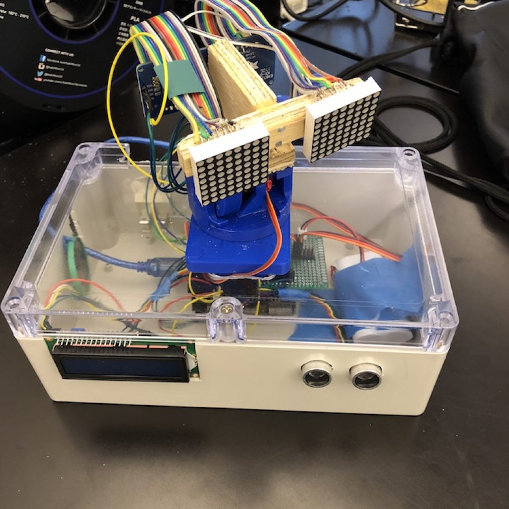
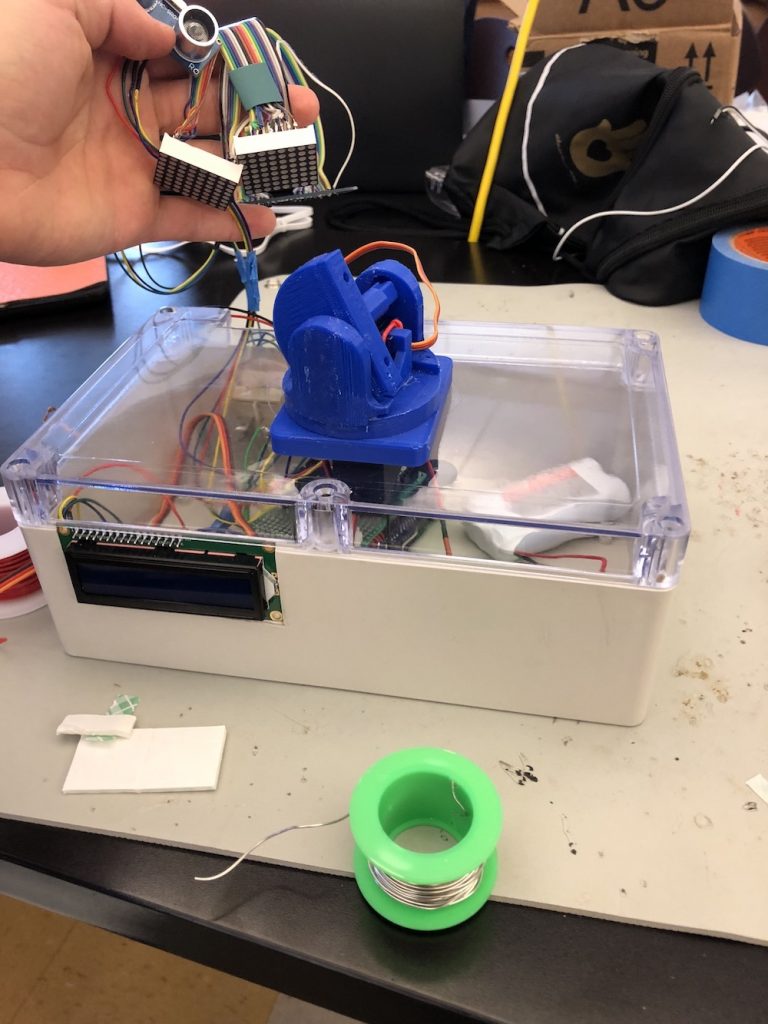
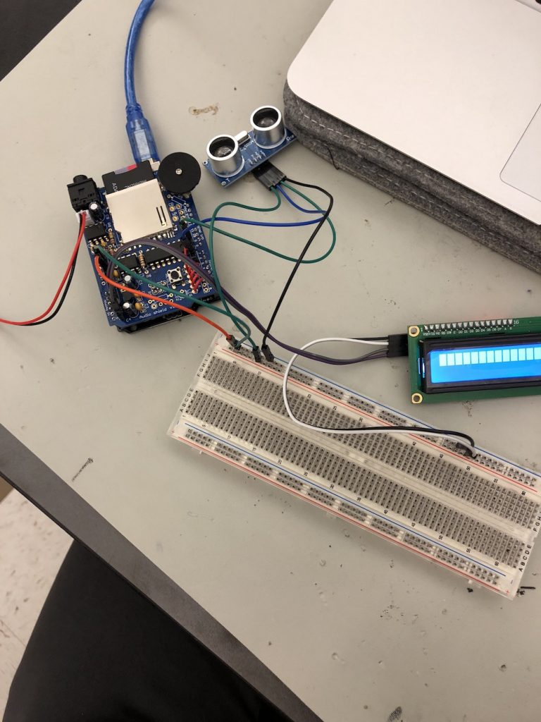
For my final milestone I completed the main build of my project. As of now my robot is coded to display “Neutral eyes” and when something gets close to it, shys away and displays “scared eyes.” From my last milestone I completed the head and mounted the eyes. I finished placing all of the other components as well. I worked on the code and created a bitmap for the two eye states. I then compiled the code for the eyes and the servos. I ran into some problems combining the codes. The timers for the servos were interfering with the LED timers. I was able to fix this by simply using a different servo library.
#include <Wire.h>
#include <LiquidCrystal_I2C.h>
#include <Wire.h>
#include <Adafruit_GFX.h>
#include “Adafruit_LEDBackpack.h”
Adafruit_8x16minimatrix matrix = Adafruit_8x16minimatrix();
LiquidCrystal_I2C lcd(0x3F, 2, 1, 0, 4, 5, 6, 7, 3, POSITIVE) ;
// Pins
const int TRIG_PIN = 7;
const int ECHO_PIN = 8;
unsigned long t1;
unsigned long t2;
unsigned long pulse_width;
float cm;
float inches;
// Anything over 400 cm (23200 us pulse) is “out of range”
const unsigned int MAX_DIST = 23200;
#include <Servo.h>
Servo servo1;
Servo servo2;
int servoPos = 0;
void setup ()
{
lcd.begin(16, 2) ;
lcd.clear();
lcd.print(“Hello, Joshua”) ;
// The Trigger pin will tell the sensor to range find
pinMode(TRIG_PIN, OUTPUT);
digitalWrite(TRIG_PIN, LOW);
servo1.attach(A0);
servo2.attach(A1);
//while (!Serial);
Serial.begin(9600);
matrix.begin(0x70); // pass in the address
}
static const uint8_t PROGMEM
Neutraleyes[] =
{ B00000000,
B00011000,
B00111100,
B01100110,
B01100110,
B00111100,
B00011000,
B00000000
},
Suprised[] =
{ B00000000,
B00111100,
B01000010,
B01011010,
B01011010,
B01000010,
B00111100,
B00000000
};
void loop () {
// Hold the trigger pin high for at least 10 us
digitalWrite(TRIG_PIN, HIGH);
delayMicroseconds(10);
digitalWrite(TRIG_PIN, LOW);
// Wait for pulse on echo pin
while ( digitalRead(ECHO_PIN) == 0 );
// Measure how long the echo pin was held high (pulse width)
// Note: the micros() counter will overflow after ~70 min
t1 = micros();
while ( digitalRead(ECHO_PIN) == 1);
t2 = micros();
pulse_width = t2 – t1;
// Calculate distance in centimeters and inches. The constants
// are found in the datasheet, and calculated from the assumed speed
//of sound in air at sea level (~340 m/s).
inches = pulse_width / 148.0;
if (inches > 9) {
// do regular eyes
Serial.println(“neutral”);
matrix.clear();
matrix.drawBitmap(0, 8, Neutraleyes, 8, 8, LED_ON);
matrix.drawBitmap(0, 0, Neutraleyes, 8, 8, LED_ON);
matrix.writeDisplay();
servo1.write(180);
servo2.write(90);
}
else {
// do suprised eyes
Serial.println(“suprised”);
matrix.clear();
matrix.drawBitmap(0, 8, Suprised, 8, 8, LED_ON);
matrix.drawBitmap(0, 0, Suprised, 8, 8, LED_ON);
matrix.writeDisplay();
servo1.write(0);
servo2.write(0);
}
// Wait at least 60ms before next measurement
delay(60);
//
// servo1.write(random(0,90));
// servo2.write(random(0,90));
// servo3.write(servoPos);
// servo4.write(servoPos);
//delay(500);
}
Third Milestone
Second Milestone
First Milestone
Starter Project

For my starter project I completed the Mini “Persistence of Vision” kit (4th edition). The device works by displaying an image via 8 RGB LEDs. Which blink, flashing an image that can be deciphered as the device is waved horizontally.
This was a good, simple project that acted as my formal introduction to the world of engineering and soldering.
The first components I soldered to the PCB board were three 2.2K resistors. These current resistors control and balance the amount of electricity to the transistors. So that they do not get overloaded by the microcontroller. Next smaller, 47𝝮 resistors where soldered to lower the current to the LEDs. Then I added two zener diodes. A diode only allows current to travel in one direction. These diodes are used to help regulate voltage on the USB data lines. In order to stabilize output voltage a ceramic capacitor was used, this also filters out high frequency noise helping the battery. To cancel out low frequency noise I used two electrolytic capacitors. These also stabilize input and output voltages. Three transistors are soldered to the PCB board, these magnify the signal to the LEDs by over 100x. To control the speed of the blinking LEDs, a Potentiometer, which rotates to adjust resistance (Volume knob!). A 12MHz crystal is used as the “timekeeper.” Just like the quartz crystal in a watch, this crystal is able to flip through all the LEDs at a consistent speed. Finally the eight LEDs are all soldered to their designated positions on the PCB board. Lastly, the 28 pin socket was soldered and the appropriate Atmel ATMega328 microcontroller was locked into place.
In order to get the device to turn on all the miniPOV needs is a battery. The wires of the battery were connected to the PCB board via a JST connecter.
After completing the device I was able to play around with the code and re-program the microcontroller because of the custom bootloader used in the kit.