MIDI Controller
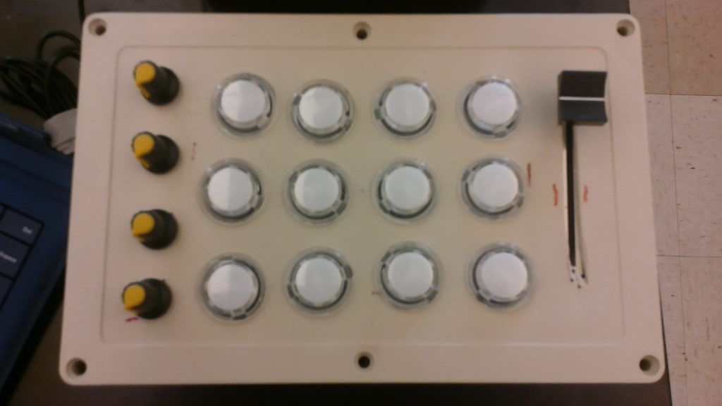
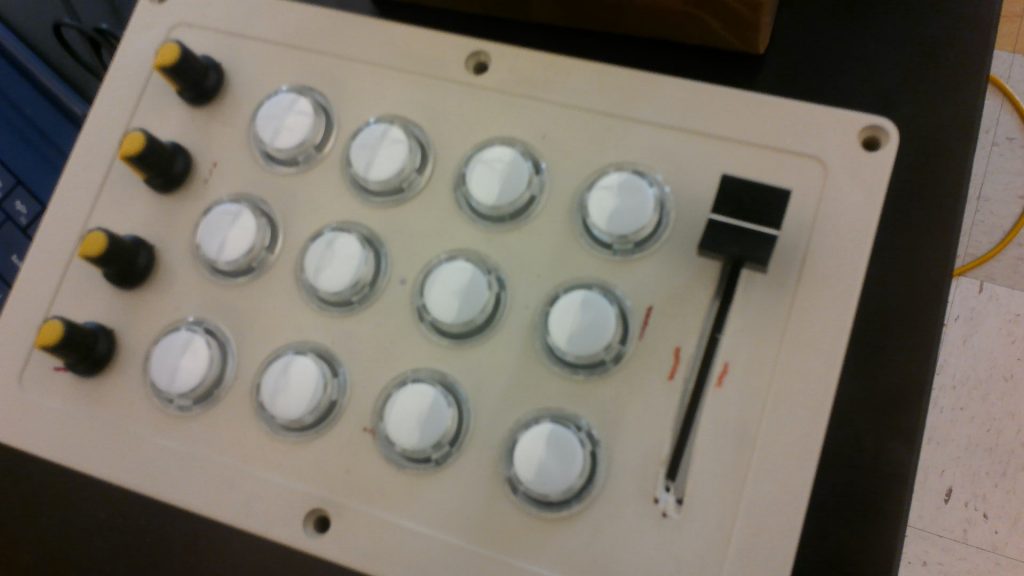
My main project is a MIDI (Musical Instrument Digital Interface) Controller. It uses buttons, knobs, and faders to send serial signals into my computer. These signals get converted to MIDI and then get interpreted into sound by a DAW (Digital Audio Workstation).
Engineer
Josh D.
Area of Interest
Mechanical Engineering
School
SAR High School
Grade
Incoming Junior
Reflection
Over the course of my time at BlueStamp, I developed many fundamental engineering skills. I always loved both engineering and music and I always wanted to combine my two hobbies. I planned my project very carefully and by the time I began I had a clear vision of what I wanted to build. In order to bring this vision to life, I learned about both mechanical design and programming. I also learned to use everything available to me to solve problems in unconventional ways. At the start of the program, I was very inexperienced in the world of electronics, however, now I feel like I could design and build my own projects. I can’t wait to keep progressing and make more amazing creations.
Final Milestone
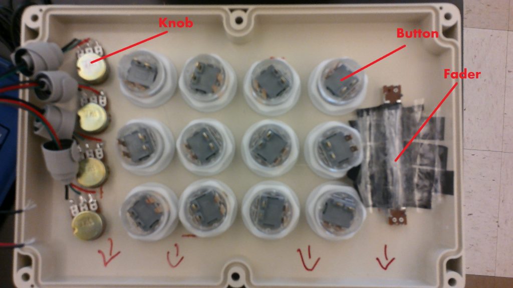
For my final milestone, I attached all of my components to the Arduino and installed everything into the box. (A list of components and all tools used can be found in the dropdown below). Each button has four wires going out of it, and each potentiometer has three. (See Figure 1). The first two button wires are for the LED. One of them goes to power and the other to ground. The next two are for the button itself. One goes to power, and the other splits into a pull-down resistor to ground, and a wire to the Arduino. A pull-down resistor takes a signal that may not be exactly 1 or 0 and “pulls” it to the proper levels. The potentiometers have one wire to power, one to ground, and one to the Arduino. While completing this step of the project, I had trouble getting all of the wires to stay in the box. To solve this, I used a mixture of tape and Velcro to stick everything together. (See Figure 2). It took me a lot of tries but in the end I got everything to work perfectly. My next step is to add a small LCD screen which will display the value of each potentiometer. I have to program the LCD and figure out how to communicate with the LCD via I2C. I am not currently sure how I am going to do this but I cannot wait to continue improving my project.
Materials
1x Arduino Uno R3
12x 24mm Arcade Buttons
4x Potentiometers (10k)
1x Sliding Potentiometer (10k)
12x Resistors (4.7k)
Tools
Drill with spade bit
Dremel with cutting tip
Soldering Iron

Figure 1: Full Wiring Diagram

Figure 2: Picture of the Wiring inside the box
// Basic MIDI Controller code for reading all of the Arduino’s digital and analogue inputs

// and sending them as MIDI messages to the host PC.

//

//Author: Josh Dauber

//Adapted From: Michael Balzer and Tim Crawford

//

//</span

// This work is licensed under a Creative Commons Attribution-NonCommercial-ShareAlike 3.0 Unported License.

// See http://creativecommons.org/licenses/by-nc-sa/3.0/ for license details.

#if defined(__AVR_ATmega1280__) || defined(__AVR_ATmega2560__)

#define ARDUINO_MEGA

#elif defined(__AVR_AT90USB646__)

#define TEENSY_PLUS_PLUS

#elif defined(__AVR_ATmega32U4__)

#define TEENSY_2

#elif defined(__AVR_AT90USB1286__)

#define TEENSY_PLUS_PLUS_2

#else

#define ARDUINO

#endif

// Uncomment this line to send debug messages to the serial monitor

//#define DEBUG

// Uncomment this line to enable outputs corresponding to the MIDI Fighter so MF mappings can be used in Traktor.

//#define MIDI_FIGHTER

//#define FASTADC

// defines for setting and clearing register bits

#ifndef cbi

#define cbi(sfr, bit) (_SFR_BYTE(sfr) &= ~_BV(bit))

#endif

#ifndef sbi

#define sbi(sfr, bit) (_SFR_BYTE(sfr) |= _BV(bit))

#endif

// MIDI mapping taken from http://www.nortonmusic.com/midi_cc.html

#define MIDI_CC_MODULATION 0x01

#define MIDI_CC_BREATH 0x02

#define MIDI_CC_VOLUME 0x07

#define MIDI_CC_BALANCE 0x08

#define MIDI_CC_PAN 0x0A</span

#define MIDI_CC_EXPRESSION 0x0B

#define MIDI_CC_EFFECT1 0x0C

#define MIDI_CC_EFFECT2 0x0D

#define MIDI_CC_GENERAL1 0x0E

#define MIDI_CC_GENERAL2 0x0F

#define MIDI_CC_GENERAL3 0x10

#define MIDI_CC_GENERAL4 0x11

#define MIDI_CC_GENERAL5 0x12

#define MIDI_CC_GENERAL6 0x13

#define MIDI_CC_GENERAL7 0x14

#define MIDI_CC_GENERAL8 0x15

#define MIDI_CC_GENERAL9 0x16

#define MIDI_CC_GENERAL10 0x17

#define MIDI_CC_GENERAL11 0x18

#define MIDI_CC_GENERAL12 0x19

#define MIDI_CC_GENERAL13 0x1A

#define MIDI_CC_GENERAL14 0x1B

#define MIDI_CC_GENERAL15 0x1C

#define MIDI_CC_GENERAL16 0x1D

#define MIDI_CC_GENERAL17 0x1E

#define MIDI_CC_GENERAL18 0x1F

#define MIDI_CC_GENERAL1_FINE 0x2E

#define MIDI_CC_GENERAL2_FINE 0x2F

#define MIDI_CC_GENERAL3_FINE 0x30

#define MIDI_CC_GENERAL4_FINE 0x31

#define MIDI_CC_GENERAL5_FINE 0x32

#define MIDI_CC_GENERAL6_FINE 0x33

#define MIDI_CC_GENERAL7_FINE 0x34

#define MIDI_CC_GENERAL8_FINE 0x35

#define MIDI_CC_GENERAL9_FINE 0x36

#define MIDI_CC_GENERAL10_FINE 0x37

#define MIDI_CC_GENERAL11_FINE 0x38

#define MIDI_CC_GENERAL12_FINE 0x39

#define MIDI_CC_GENERAL13_FINE 0x3A

#define MIDI_CC_GENERAL14_FINE 0x3B

#define MIDI_CC_GENERAL15_FINE 0x3C

#define MIDI_CC_GENERAL16_FINE 0x3D

#define MIDI_CC_GENERAL17_FINE 0x3E

#define MIDI_CC_GENERAL18_FINE 0x3F

#define MIDI_CC_SUSTAIN 0x40

#define MIDI_CC_REVERB 0x5B

#define MIDI_CC_CHORUS 0x5D

#define MIDI_CC_CONTROL_OFF 0x79

#define MIDI_CC_NOTES_OFF 0x78

#define NOTE_C0 0x00 // 0

#define NOTE_C1 0x12 // 18

#define NOTE_C2 0x24 // 36

#if defined(ARDUINO_MEGA)

// Number of digital inputs. Can be anywhere from 0 to 68.

#define NUM_DI 52

// Number of analogue inputs. Can be anywhere from 0 to 16.

#define NUM_AI 16

#elif defined(TEENSY_PLUS_PLUS)

// Number of digital inputs. Can be anywhere from 0 to 46.

#define NUM_DI 38

// Number of analogue inputs. Can be anywhere from 0 to 8.

#define NUM_AI 8

#elif defined(TEENSY_2)

// Number of digital inputs. Can be anywhere from 0 to 25.

#define NUM_DI 13

// Number of analogue inputs. Can be anywhere from 0 to 12.

#define NUM_AI 12

#elif defined(TEENSY_PLUS_PLUS_2)

// Number of digital inputs. Can be anywhere from 0 to 46.

#define NUM_DI 38

// Number of analogue inputs. Can be anywhere from 0 to 8.

#define NUM_AI 8

#else //when it is Arduino

// Number of digital inputs. Can be anywhere from 0 to 18.

#define NUM_DI 12

// Number of analogue inputs. Can be anywhere from 0 to 6.

#define NUM_AI 5

#endif

#if defined(MIDI_FIGHTER) && defined(ARDUINO)

#define MIDI_CHANNEL 3

// First note, starting from lower left button

#define NOTE NOTE_C2

// When mapping to a MIDI Fighter we need to skip a row of buttons. Set this from 0-3 to define which row to skip.

// Rows are ordered from bottom to top (same as the MIDI Fighter’s button layout).

#define SKIP_ROW 2

// This pin order corresponds to the bottom left button being zero, increasing by one as we move from left to right, bottom to top

// 8 9 10 11

// 4 5 6 7

// 0 1 2 3

// This array size must match NUM_DI above.

#define DIGITAL_PIN_ORDER 10, 11, 12, 13, 6, 7, 8, 9, 2, 3, 4, 5

#else

#define MIDI_CHANNEL 1

// First note, starting from upper left button

#define NOTE NOTE_C0

// This pin order corresponds to the top left button being zero, increasing by one as we move from left to right, top to bottom

// 0 1 2 3

// 4 5 6 7

// 8 9 10 11

// This array size must match NUM_DI above.

#if defined(ARDUINO_MEGA)

#define DIGITAL_PIN_ORDER 2, 3, 4, 5, 6, 7, 8, 9, 10, 11, 12, 13, 14, 15, 16, 17, 18, 19, 20, 21, 22, 23, 24, 25, 26, 27, 28, 29, 30, 31, 32, 33, 34, 35, 36, 37, 38, 39, 40, 41, 42, 43, 44, 45, 46, 47, 48, 49, 50, 51, 52, 53

#elif defined(TEENSY_PLUS_PLUS)

#define DIGITAL_PIN_ORDER 0, 1, 2, 3, 4, 5, 6, 7, 8, 9, 10, 11, 12, 13, 14, 15, 16, 17, 18, 19, 20, 21, 22, 23, 24, 25, 26, 27, 28, 29, 30, 31, 32, 33, 34, 35, 36, 37

#elif defined(TEENSY_2)

#define DIGITAL_PIN_ORDER 0, 1, 2, 3, 4, 5, 6, 7, 8, 9, 10, 11, 12

#elif defined(TEENSY_PLUS_PLUS_2)

#define DIGITAL_PIN_ORDER 0, 1, 2, 3, 4, 5, 6, 7, 8, 9, 10, 11, 12, 13, 14, 15, 16, 17, 18, 19, 20, 21, 22, 23, 24, 25, 26, 27, 28, 29, 30, 31, 32, 33, 34, 35, 36, 37

#else//arduino uno

#define DIGITAL_PIN_ORDER 2, 3, 4, 5, 6, 7, 8, 9, 10, 11, 12, 13

#endif

#endif

#if defined(ARDUINO_MEGA)

#define ANALOGUE_PIN_ORDER A0, A1, A2, A3, A4, A5, A6, A7, A8, A9, A10, A11, A12, A13, A14, A15

#elif defined(TEENSY_PLUS_PLUS)

#define ANALOGUE_PIN_ORDER 0, 1, 2, 3, 4, 5, 6, 7

#elif defined(TEENSY_2)

#define ANALOGUE_PIN_ORDER 0, 1, 2, 3, 4, 5, 6, 7, 8, 9, 10, 11

#elif defined(TEENSY_PLUS_PLUS_2)

#define ANALOGUE_PIN_ORDER 0, 1, 2, 3, 4, 5, 6, 7

#else//arduino uno

#define ANALOGUE_PIN_ORDER A0, A1, A2, A3, A4

#endif

#if defined(TEENSY_PLUS_PLUS) || defined(TEENSY_2) || defined(TEENSY_PLUS_PLUS_2)

#define LED_PIN PIN_D6

#else

#define LED_PIN LED_BUILTIN

#endif

#define MIDI_CC MIDI_CC_GENERAL1

// Comment this line out to disable button debounce logic.

// See http://arduino.cc/en/Tutorial/Debounce on what debouncing is used for.

#define DEBOUNCE

// Debounce time length in milliseconds

#define DEBOUNCE_LENGTH 2

// Comment this line out to disable analogue filtering

#define ANALOGUE_FILTER

// A knob or slider movement must initially exceed this value to be recognised as an input. Note that it is

// for a 7-bit (0-127) MIDI value.

#ifdef FASTADC

#define FILTER_AMOUNT 3

#else

#define FILTER_AMOUNT 2

#endif

// Timeout is in microseconds

#define ANALOGUE_INPUT_CHANGE_TIMEOUT 250000

// Array containing a mapping of digital pins to channel index.

byte digitalInputMapping[NUM_DI] = {DIGITAL_PIN_ORDER};

// Array containing a mapping of analogue pins to channel index. This array size must match NUM_AI above.

byte analogueInputMapping[NUM_AI] = {ANALOGUE_PIN_ORDER};

// Contains the current state of the digital inputs.

byte digitalInputs[NUM_DI];

// Contains the current value of the analogue inputs.

byte analogueInputs[NUM_AI];

// Variable to hold temporary digital reads, used for debounce logic.

byte tempDigitalInput;

// Variable to hold temporary analogue values, used for analogue filtering logic.

byte tempAnalogueInput;

// Preallocate the for loop index so we don’t keep reallocating it for every program iteration.

byte i = 0;

byte digitalOffset = 0;

// Variable to hold difference between current and new analogue input values.

byte analogueDiff = 0;

// This is used as a flag to indicate that an analogue input is changing.

boolean analogueInputChanging[NUM_AI];

// Time the analogue input was last moved

unsigned long analogueInputTimer[NUM_AI];

#ifdef DEBUG

unsigned long loopTime = 0;

unsigned long serialSendTime = 0;

#endif

void setup()

{

// Taken from http://www.arduino.cc/cgi-bin/yabb2/YaBB.pl?num=1208715493/11

#ifdef FASTADC

// set prescale to 16

sbi(ADCSRA,ADPS2) ;

cbi(ADCSRA,ADPS1) ;

cbi(ADCSRA,ADPS0) ;

#endif

// Only enable serial on the Arduino or when debugging. The Teensy board should be set as a usb-midi device so serial is not needed.

#if defined(ARDUINO) || defined(ARDUINO_MEGA) || defined(DEBUG)

// Enable serial I/O at 115200 kbps. This is faster than the standard MIDI rate of 31250 kbps.

// The PC application which we connect to will automatically take the higher sample rate and send MIDI

// messages out at the correct rate. We only send things faster in case there is any latency.

Serial.begin(115200);

#endif

// Initialise each digital input channel.

for (i = 0; i < NUM_DI; i++)

{

// Set the pin direction to input.

pinMode(digitalInputMapping[i], INPUT);

// Don’t enable pullup resistor on LED_PIN, as the LED and resistor will always pull it low, meaning the input won’t work.

// Instead an external pulldown resistor must be used on LED_PIN.

// NOTE: This will cause all of the high/low logic for LED_PIN to be inverted.

if (digitalInputMapping[i] != LED_PIN)

{

// Enable the pull-up resistor. This call must come after the above pinMode call.

digitalWrite(digitalInputMapping[i], HIGH);

}

// Initialise the digital state with a read to the input pin.

digitalInputs[i] = digitalRead(digitalInputMapping[i]);

}

// Initialise each analogue input channel.

for (i = 0; i < NUM_AI; i++)

{

// Set the pin direction to input.

pinMode(analogueInputMapping[i], INPUT);

// Initialise the analogue value with a read to the input pin.

analogueInputs[i] = analogRead(analogueInputMapping[i]);

// Assume no analogue inputs are active

analogueInputChanging[i] = false;

analogueInputTimer[i] = 0;

}

#ifdef DEBUG

serialSendTime = millis();

#endif

}

void loop()

{

#ifdef DEBUG

loopTime = micros();

#endif

for (i = 0; i < NUM_DI; i++)

{

#ifdef MIDI_FIGHTER

if (i >= SKIP_ROW * 4)

{

digitalOffset = i + 4;

}

else

{

#endif

digitalOffset = i;

#ifdef MIDI_FIGHTER

}

#endif

// Read the current state of the digital input and store it temporarily.

tempDigitalInput = digitalRead(digitalInputMapping[i]);

// Check if the last state is different to the current state.

if (digitalInputs[i] != tempDigitalInput)

{

#ifdef DEBOUNCE

// Wait for a short period of time, and then take a second reading from the input pin.

delay(DEBOUNCE_LENGTH);

// If the second reading is the same as the initial reading, assume it must be true.

if (tempDigitalInput == digitalRead(digitalInputMapping[i]))

{

#endif

// Record the new digital input state.

digitalInputs[i] = tempDigitalInput;

// Moved from HIGH to LOW (button pressed)

if (digitalInputs[i] == 0)

{

// All the digital inputs use pullup resistors, except LED_PIN so the logic is inverted

if (digitalInputMapping[i] != LED_PIN)

{

noteOn(MIDI_CHANNEL, NOTE + digitalOffset, 0x7F); // Channel 1, middle C, maximum velocity

}

else

{

noteOff(MIDI_CHANNEL, NOTE + digitalOffset); // Channel 1, middle C

}

}

// Moved from LOW to HIGH (button released)

else

{

// All the digital inputs use pullup resistors, except LED_PIN so the logic is inverted

if (digitalInputMapping[i] != LED_PIN)

{

noteOff(MIDI_CHANNEL, NOTE + digitalOffset); // Channel 1, middle C

}

else

{

noteOn(MIDI_CHANNEL, NOTE + digitalOffset, 0x7F); // Channel 1, middle C, maximum velocity

}

}

#ifdef DEBOUNCE

}

#endif

}

}

/*

* Analogue input logic:

* The Arduino uses a 10-bit (0-1023) analogue to digital converter (ADC) on each of its analogue inputs.

* The ADC isn’t very high resolution, so if a pot is in a position such that the output voltage is ‘between’

* what it can detect (say 2.505V or about 512.5 on a scale of 0-1023) then the value read will constantly

* fluctuate between two integers (in this case 512 and 513).

*

* If we’re simply looking for a change in the analogue input value like in the digital case above, then

* there will be cases where the value is always changing, even though the physical input isn’t being moved.

* This will in turn send out a constant stream of MIDI messages to the connected software which may be problematic.

*

* To combat this, we require that the analogue input value must change by a certain threshold amount before

* we register that it is actually changing. This is good in avoiding a constantly fluctuating value, but has

* the negative effect of a reduced input resolution. For example if the threshold amount was 2 and we slowly moved

* a slider through it’s full range, we would only detect every second value as a change, in effect reducing the

* already small 7-bit MIDI value to a 6-bit MIDI value.

*

* To get around this problem but still use the threshold logic, a timer is used. Initially the analogue input

* must exceed the threshold to be detected as an input. Once this occurs, we then read every value coming from the

* analogue input (not just those exceeding a threshold) giving us full 7-bit resolution. At the same time the

* timer is started. This timer is used to keep track of whether an input hasn’t been moved for a certain time

* period. If it has been moved, the timer is restarted. If no movement occurs the timer is just left to run. When

* the timer expires the analogue input is assumed to be no longer moving. Subsequent movements must exceed the

* threshold amount.

*/

for (i = 0; i < NUM_AI; i++)

{

// Read the analogue input pin, dividing it by 8 so the 10-bit ADC value (0-1023) is converted to a 7-bit MIDI value (0-127).

tempAnalogueInput = analogRead(analogueInputMapping[i]) / 8;

#ifdef ANALOGUE_FILTER

// Take the absolute value of the difference between the curent and new values

analogueDiff = abs(tempAnalogueInput – analogueInputs[i]);

// Only continue if the threshold was exceeded, or the input was already changing

if ((analogueDiff > 0 && analogueInputChanging[i] == true) || analogueDiff >= FILTER_AMOUNT)

{

// Only restart the timer if we’re sure the input isn’t ‘between’ a value

// ie. It’s moved more than FILTER_AMOUNT

if (analogueInputChanging[i] == false || analogueDiff >= FILTER_AMOUNT)

{

// Reset the last time the input was moved

analogueInputTimer[i] = micros();

// The analogue input is moving

analogueInputChanging[i] = true;

}

else if (micros() – analogueInputTimer[i] > ANALOGUE_INPUT_CHANGE_TIMEOUT)

{

analogueInputChanging[i] = false;

}

// Only send data if we know the analogue input is moving

if (analogueInputChanging[i] == true)

{

// Record the new analogue value

analogueInputs[i] = tempAnalogueInput;

// Send the analogue value out on the general MIDI CC (see definitions at beginning of this file)

controlChange(MIDI_CHANNEL, MIDI_CC + i, analogueInputs[i]);

}

}

#else

if (analogueInputs[i] != tempAnalogueInput)

{

// Record the new analogue value

analogueInputs[i] = tempAnalogueInput;

// Send the analogue value out on the general MIDI CC (see definitions at beginning of this file)

controlChange(MIDI_CHANNEL, MIDI_CC + i, analogueInputs[i]);

}

#endif

}

#ifdef DEBUG

loopTime = micros() – loopTime;

// Print the loop execution time once per second

if (millis() – serialSendTime > 1000)

{

Serial.print(“Loop execution time (us): “);

Serial.println(loopTime);

serialSendTime = millis();

}

#endif

}

// Send a MIDI note on message

void noteOn(byte channel, byte pitch, byte velocity)

{

// 0x90 is the first of 16 note on channels. Subtract one to go from MIDI’s 1-16 channels to 0-15

channel += 0x90 – 1;

// Ensure we’re between channels 1 and 16 for a note on message

if (channel >= 0x90 && channel <= 0x9F)

{

#ifdef DEBUG

Serial.print(“Button pressed: “);

Serial.println(pitch);

#elif defined(TEENSY_PLUS_PLUS) || defined(TEENSY_2) || defined(TEENSY_PLUS_PLUS_2)

usbMIDI.sendNoteOn(pitch, velocity, channel);

#else

Serial.write(channel);

Serial.write(pitch);

Serial.write(velocity);

#endif

}

}

// Send a MIDI note off message

void noteOff(byte channel, byte pitch)

{

// 0x80 is the first of 16 note off channels. Subtract one to go from MIDI’s 1-16 channels to 0-15

channel += 0x80 – 1;

// Ensure we’re between channels 1 and 16 for a note off message

if (channel >= 0x80 && channel <= 0x8F)

{

#ifdef DEBUG

Serial.print(“Button released: “);

Serial.println(pitch);

#elif defined(TEENSY_PLUS_PLUS) || defined(TEENSY_2) || defined(TEENSY_PLUS_PLUS_2)

usbMIDI.sendNoteOff(pitch, 0x00, channel);

#else

Serial.write(channel);

Serial.write(pitch);

Serial.write((byte)0x00);

#endif

}

}

// Send a MIDI control change message

void controlChange(byte channel, byte control, byte value)

{

// 0xB0 is the first of 16 control change channels. Subtract one to go from MIDI’s 1-16 channels to 0-15

channel += 0xB0 – 1;

// Ensure we’re between channels 1 and 16 for a CC message

if (channel >= 0xB0 && channel <= 0xBF)

{

#ifdef DEBUG

Serial.print(control – MIDI_CC);

Serial.print(“: “);

Serial.println(value);

#elif defined(TEENSY_PLUS_PLUS) || defined(TEENSY_2) || defined(TEENSY_PLUS_PLUS_2)

usbMIDI.sendControlChange(control, value, channel);

#else

Serial.write(channel);

Serial.write(control);

Serial.write(value);

#endif

}

}
Second Milestone
For my second milestone, I have gotten one of the buttons to send a MIDI (musical instrument digital interface) input to my DAW (digital audio workstation). Eventually, I will have 12 buttons and 5 potentiometers all sending MIDI signals. When pressed, the button changes the signal on the Arduino pin from high to low. The following code triggers the arduino to send serial messages to a computer program called HairlessMIDI (see Figure 1):
      // Moved from HIGH to LOW (button pressed)

        if (digitalInputs[i] == 0)

        {

          // All the digital inputs use pullup resistors, except LED_PIN so the logic is inverted

          if (digitalInputMapping[i] != LED_PIN)

          {

            noteOn(MIDI_CHANNEL, NOTE + digitalOffset, 0x7F);

 // Channel 1, middle C, maximum velocity

          }

          else

          {

            noteOff(MIDI_CHANNEL, NOTE + digitalOffset);

 // Channel 1, middle C

          }
When the button is released code that is essentially the opposite of the above is run to cancel the MIDI signal (see Full Code). HairlessMIDI converts the serial signals into MIDI signals which it sends through a different program called LoopMIDI. LoopMIDI (see Figure 2) is a virtual MIDI port. Essentially, LoopMIDI tricks the computer into thinking that something is plugged into a MIDI port on the computer. From LoopMIDI, the signal goes into FL Studio, my digital audio workstation, which interprets the MIDI signal and uses it to play sound. While trying to accomplish this, I ran into a problem where FL studio would recognize that it was receiving a MIDI input. However, the MIDI input was incomplete and did not include note and velocity data. To solve this, I completely changed the way in which I was sending MIDI out from the Arduino. At first, I was using an Arduino MIDI library to send MIDI signals out from the Arduino to the computer. However, in the end I used separately defined notes within the code to trigger MIDI signals. Although I had a lot of trouble getting the MIDI input to work properly, I am very excited that it works and I can not wait to continue working on my project.
Full code and a flowchart demonstrating the process are attached to the left. (see Figure 4 and Code Dropdown Menu).
// Moved from HIGH to LOW (button pressed)
if (digitalInputs[i] == 0)
{
// All the digital inputs use pullup resistors, except LED_PIN so the logic is inverted
if (digitalInputMapping[i] != LED_PIN)
{
noteOn(MIDI_CHANNEL, NOTE + digitalOffset, 0x7F);
// Channel 1, middle C, maximum velocity
}
else
{
noteOff(MIDI_CHANNEL, NOTE + digitalOffset);
// Channel 1, middle C
}

Figure 1: A screenshot of HairlessMIDI with the output set to the LoopMIDI virtual MIDI port

Figure 2: A screenshot of LoopMIDI virtual MIDI port with one MIDI port active.

Figure 3: A flowchart showing the process of turning a button press into an audio output
// Basic MIDI Controller code for reading all of the Arduino's digital and analogue inputs
// and sending them as MIDI messages to the host PC.
//
//Author: Josh Dauber
//Adapted From: Michael Balzer and Tim Crawford
//
// 2018-07-12 Edited to work for just 1 digital input and 0 analog inputs on Arduino Uno
//
// This work is licensed under a Creative Commons Attribution-NonCommercial-ShareAlike 3.0 Unported License.
// See http://creativecommons.org/licenses/by-nc-sa/3.0/ for license details.

#if defined(__AVR_ATmega1280__) || defined(__AVR_ATmega2560__)
#define ARDUINO_MEGA
#elif defined(__AVR_AT90USB646__)
#define TEENSY_PLUS_PLUS
#elif defined(__AVR_ATmega32U4__)
#define TEENSY_2
#elif defined(__AVR_AT90USB1286__)
#define TEENSY_PLUS_PLUS_2
#else
#define ARDUINO
#endif

// Uncomment this line to send debug messages to the serial monitor
//#define DEBUG

// Uncomment this line to enable outputs corresponding to the MIDI Fighter so MF mappings can be used in Traktor.
//#define MIDI_FIGHTER

//#define FASTADC
// defines for setting and clearing register bits
#ifndef cbi
#define cbi(sfr, bit) (_SFR_BYTE(sfr) &= ~_BV(bit))
#endif
#ifndef sbi
#define sbi(sfr, bit) (_SFR_BYTE(sfr) |= _BV(bit))
#endif

// MIDI mapping taken from http://www.nortonmusic.com/midi_cc.html
#define MIDI_CC_MODULATION 0x01
#define MIDI_CC_BREATH 0x02
#define MIDI_CC_VOLUME 0x07
#define MIDI_CC_BALANCE 0x08
#define MIDI_CC_PAN 0x0A
#define MIDI_CC_EXPRESSION 0x0B
#define MIDI_CC_EFFECT1 0x0C
#define MIDI_CC_EFFECT2 0x0D

#define MIDI_CC_GENERAL1 0x0E
#define MIDI_CC_GENERAL2 0x0F
#define MIDI_CC_GENERAL3 0x10
#define MIDI_CC_GENERAL4 0x11
#define MIDI_CC_GENERAL5 0x12
#define MIDI_CC_GENERAL6 0x13
#define MIDI_CC_GENERAL7 0x14
#define MIDI_CC_GENERAL8 0x15
#define MIDI_CC_GENERAL9 0x16
#define MIDI_CC_GENERAL10 0x17
#define MIDI_CC_GENERAL11 0x18
#define MIDI_CC_GENERAL12 0x19
#define MIDI_CC_GENERAL13 0x1A
#define MIDI_CC_GENERAL14 0x1B
#define MIDI_CC_GENERAL15 0x1C
#define MIDI_CC_GENERAL16 0x1D
#define MIDI_CC_GENERAL17 0x1E
#define MIDI_CC_GENERAL18 0x1F

#define MIDI_CC_GENERAL1_FINE 0x2E
#define MIDI_CC_GENERAL2_FINE 0x2F
#define MIDI_CC_GENERAL3_FINE 0x30
#define MIDI_CC_GENERAL4_FINE 0x31
#define MIDI_CC_GENERAL5_FINE 0x32
#define MIDI_CC_GENERAL6_FINE 0x33
#define MIDI_CC_GENERAL7_FINE 0x34
#define MIDI_CC_GENERAL8_FINE 0x35
#define MIDI_CC_GENERAL9_FINE 0x36
#define MIDI_CC_GENERAL10_FINE 0x37
#define MIDI_CC_GENERAL11_FINE 0x38
#define MIDI_CC_GENERAL12_FINE 0x39
#define MIDI_CC_GENERAL13_FINE 0x3A
#define MIDI_CC_GENERAL14_FINE 0x3B
#define MIDI_CC_GENERAL15_FINE 0x3C
#define MIDI_CC_GENERAL16_FINE 0x3D
#define MIDI_CC_GENERAL17_FINE 0x3E
#define MIDI_CC_GENERAL18_FINE 0x3F

#define MIDI_CC_SUSTAIN 0x40
#define MIDI_CC_REVERB 0x5B
#define MIDI_CC_CHORUS 0x5D
#define MIDI_CC_CONTROL_OFF 0x79
#define MIDI_CC_NOTES_OFF 0x78

#define NOTE_C0 0x00 // 0
#define NOTE_C1 0x12 // 18
#define NOTE_C2 0x24 // 36

#if defined(ARDUINO_MEGA)
// Number of digital inputs. Can be anywhere from 0 to 68.
#define NUM_DI 52
#elif defined(TEENSY_PLUS_PLUS)
// Number of digital inputs. Can be anywhere from 0 to 46.
#define NUM_DI 38
// Number of analogue inputs. Can be anywhere from 0 to 8.
#elif defined(TEENSY_2)
// Number of digital inputs. Can be anywhere from 0 to 25.
#define NUM_DI 13
#elif defined(TEENSY_PLUS_PLUS_2)
// Number of digital inputs. Can be anywhere from 0 to 46.
#define NUM_DI 38
#else //when it is Arduino
// Number of digital inputs. Can be anywhere from 0 to 18.
//#define NUM_DI 12
#define NUM_DI 1
// Number of analogue inputs. Can be anywhere from 0 to 6.
#endif

#if defined(MIDI_FIGHTER) && defined(ARDUINO)
#define MIDI_CHANNEL 3
// First note, starting from lower left button
#define NOTE NOTE_C2
// When mapping to a MIDI Fighter we need to skip a row of buttons. Set this from 0-3 to define which row to skip.
// Rows are ordered from bottom to top (same as the MIDI Fighter's button layout).
#define SKIP_ROW 2
// This pin order corresponds to the bottom left button being zero, increasing by one as we move from left to right, bottom to top
// 8 9 10 11
// 4 5 6 7
// 0 1 2 3
// This array size must match NUM_DI above.
#define DIGITAL_PIN_ORDER 10, 11, 12, 13, 6, 7, 8, 9, 2, 3, 4, 5
#else
#define MIDI_CHANNEL 1
// First note, starting from upper left button
#define NOTE NOTE_C0
// This pin order corresponds to the top left button being zero, increasing by one as we move from left to right, top to bottom
// 0 1 2 3
// 4 5 6 7
// 8 9 10 11
// This array size must match NUM_DI above.
#if defined(ARDUINO_MEGA)
#define DIGITAL_PIN_ORDER 2, 3, 4, 5, 6, 7, 8, 9, 10, 11, 12, 13, 14, 15, 16, 17, 18, 19, 20, 21, 22, 23, 24, 25, 26, 27, 28, 29, 30, 31, 32, 33, 34, 35, 36, 37, 38, 39, 40, 41, 42, 43, 44, 45, 46, 47, 48, 49, 50, 51, 52, 53
#elif defined(TEENSY_PLUS_PLUS)
#define DIGITAL_PIN_ORDER 0, 1, 2, 3, 4, 5, 6, 7, 8, 9, 10, 11, 12, 13, 14, 15, 16, 17, 18, 19, 20, 21, 22, 23, 24, 25, 26, 27, 28, 29, 30, 31, 32, 33, 34, 35, 36, 37
#elif defined(TEENSY_2)
#define DIGITAL_PIN_ORDER 0, 1, 2, 3, 4, 5, 6, 7, 8, 9, 10, 11, 12
#elif defined(TEENSY_PLUS_PLUS_2)
#define DIGITAL_PIN_ORDER 0, 1, 2, 3, 4, 5, 6, 7, 8, 9, 10, 11, 12, 13, 14, 15, 16, 17, 18, 19, 20, 21, 22, 23, 24, 25, 26, 27, 28, 29, 30, 31, 32, 33, 34, 35, 36, 37
#else//arduino uno
// #define DIGITAL_PIN_ORDER 2, 3, 4, 5, 6, 7, 8, 9, 10, 11, 12, 13
#define DIGITAL_PIN_ORDER 2
#endif
#endif

#if defined(TEENSY_PLUS_PLUS) || defined(TEENSY_2) || defined(TEENSY_PLUS_PLUS_2)
#define LED_PIN PIN_D6
#else
// #define LED_PIN 13
#define LED_PIN LED_BUILTIN
#endif

#define MIDI_CC MIDI_CC_GENERAL1

// Comment this line out to disable button debounce logic.
// See http://arduino.cc/en/Tutorial/Debounce on what debouncing is used for.
#define DEBOUNCE
// Debounce time length in milliseconds
#define DEBOUNCE_LENGTH 2

// Array containing a mapping of digital pins to channel index.
byte digitalInputMapping[NUM_DI] = {DIGITAL_PIN_ORDER};

// Contains the current state of the digital inputs.
byte digitalInputs[NUM_DI];
// Variable to hold temporary digital reads, used for debounce logic.
byte tempDigitalInput;

// Preallocate the for loop index so we don't keep reallocating it for every program iteration.
byte i = 0;
byte digitalOffset = 0;

#ifdef DEBUG
unsigned long loopTime = 0;
unsigned long serialSendTime = 0;
#endif

void setup()
{
// Taken from http://www.arduino.cc/cgi-bin/yabb2/YaBB.pl?num=1208715493/11
#ifdef FASTADC
// set prescale to 16
sbi(ADCSRA,ADPS2) ;
cbi(ADCSRA,ADPS1) ;
cbi(ADCSRA,ADPS0) ;
#endif

// Only enable serial on the Arduino or when debugging. The Teensy board should be set as a usb-midi device so serial is not needed.
#if defined(ARDUINO) || defined(ARDUINO_MEGA) || defined(DEBUG)
// Enable serial I/O at 115200 kbps. This is faster than the standard MIDI rate of 31250 kbps.
// The PC application which we connect to will automatically take the higher sample rate and send MIDI
// messages out at the correct rate. We only send things faster in case there is any latency.
Serial.begin(115200);
#endif

// Initialise each digital input channel.
for (i = 0; i < NUM_DI; i++)
{
// Set the pin direction to input.
pinMode(digitalInputMapping[i], INPUT);

// Don't enable pullup resistor on LED_PIN, as the LED and resistor will always pull it low, meaning the input won't work.
// Instead an external pulldown resistor must be used on LED_PIN.
// NOTE: This will cause all of the high/low logic for LED_PIN to be inverted.
if (digitalInputMapping[i] != LED_PIN)
{
// Enable the pull-up resistor. This call must come after the above pinMode call.
digitalWrite(digitalInputMapping[i], HIGH);
}

// Initialise the digital state with a read to the input pin.
digitalInputs[i] = digitalRead(digitalInputMapping[i]);
}

#ifdef DEBUG
serialSendTime = millis();
#endif
}

void loop()
{
#ifdef DEBUG
loopTime = micros();
#endif

for (i = 0; i < NUM_DI; i++)
{
#ifdef MIDI_FIGHTER
if (i >= SKIP_ROW * 4)
{
digitalOffset = i + 4;
}
else
{
#endif

digitalOffset = i;

#ifdef MIDI_FIGHTER
}
#endif

// Read the current state of the digital input and store it temporarily.
tempDigitalInput = digitalRead(digitalInputMapping[i]);

// Check if the last state is different to the current state.
if (digitalInputs[i] != tempDigitalInput)
{
#ifdef DEBOUNCE
// Wait for a short period of time, and then take a second reading from the input pin.
delay(DEBOUNCE_LENGTH);
// If the second reading is the same as the initial reading, assume it must be true.
if (tempDigitalInput == digitalRead(digitalInputMapping[i]))
{
#endif
// Record the new digital input state.
digitalInputs[i] = tempDigitalInput;

// Moved from HIGH to LOW (button pressed)
if (digitalInputs[i] == 0)
{
// All the digital inputs use pullup resistors, except LED_PIN so the logic is inverted
if (digitalInputMapping[i] != LED_PIN)
{
noteOn(MIDI_CHANNEL, NOTE + digitalOffset, 0x7F); // Channel 1, middle C, maximum velocity
}
else
{
noteOff(MIDI_CHANNEL, NOTE + digitalOffset); // Channel 1, middle C
}
}
// Moved from LOW to HIGH (button released)
else
{
// All the digital inputs use pullup resistors, except LED_PIN so the logic is inverted
if (digitalInputMapping[i] != LED_PIN)
{
noteOff(MIDI_CHANNEL, NOTE + digitalOffset); // Channel 1, middle C
}
else
{
noteOn(MIDI_CHANNEL, NOTE + digitalOffset, 0x7F); // Channel 1, middle C, maximum velocity
}
}
#ifdef DEBOUNCE
}
#endif
}
}

#ifdef DEBUG
loopTime = micros() - loopTime;

// Print the loop execution time once per second
if (millis() - serialSendTime > 1000)
{
Serial.print("Loop execution time (us): ");
Serial.println(loopTime);

serialSendTime = millis();
}
#endif
}

// Send a MIDI note on message
void noteOn(byte channel, byte pitch, byte velocity)
{
// 0x90 is the first of 16 note on channels. Subtract one to go from MIDI's 1-16 channels to 0-15
channel += 0x90 - 1;

// Ensure we're between channels 1 and 16 for a note on message
if (channel >= 0x90 && channel <= 0x9F)
{
#ifdef DEBUG
Serial.print("Button pressed: ");
Serial.println(pitch);
#elif defined(TEENSY_PLUS_PLUS) || defined(TEENSY_2) || defined(TEENSY_PLUS_PLUS_2)
usbMIDI.sendNoteOn(pitch, velocity, channel);
#else
Serial.write(channel);
Serial.write(pitch);
Serial.write(velocity);
#endif
}
}

// Send a MIDI note off message
void noteOff(byte channel, byte pitch)
{
// 0x80 is the first of 16 note off channels. Subtract one to go from MIDI's 1-16 channels to 0-15
channel += 0x80 - 1;

// Ensure we're between channels 1 and 16 for a note off message
if (channel >= 0x80 && channel <= 0x8F)
{
#ifdef DEBUG
Serial.print("Button released: ");
Serial.println(pitch);
#elif defined(TEENSY_PLUS_PLUS) || defined(TEENSY_2) || defined(TEENSY_PLUS_PLUS_2)
usbMIDI.sendNoteOff(pitch, 0x00, channel);
#else
Serial.write(channel);
Serial.write(pitch);
Serial.write((byte)0x00);
#endif
}
}

// Send a MIDI control change message
void controlChange(byte channel, byte control, byte value)
{
// 0xB0 is the first of 16 control change channels. Subtract one to go from MIDI's 1-16 channels to 0-15
channel += 0xB0 - 1;

// Ensure we're between channels 1 and 16 for a CC message
if (channel >= 0xB0 && channel <= 0xBF)
{
#ifdef DEBUG
Serial.print(control - MIDI_CC);
Serial.print(": ");
Serial.println(value);
#elif defined(TEENSY_PLUS_PLUS) || defined(TEENSY_2) || defined(TEENSY_PLUS_PLUS_2)
usbMIDI.sendControlChange(control, value, channel);
#else
Serial.write(channel);
Serial.write(control);
Serial.write(value);
#endif
}
}
Button Wiring
Button Wiring Explained
The button has four wires running out of it. Two of the wires are for the LED. One goes to power and the other to ground. The other two wires are for the button itself. One goes to power and the other splits into a pull-down resistor to ground and a wire to a digital pin on the Arduino.
First Milestone