
Main Project:
For My main project I am creating a Raspberry Pi arcade system. The Idea was that I would get experience in the following categories:
- Arduino : Inputs and Outputs
- Inputs with the joystick shield
- Outputs with the bluetooth module
- Raspberry Pi: learn how to use the raspberry pi and pygame (python module for creating games)
- Learn how to use cad to make a case for both
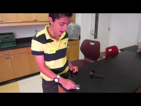
I’m Jonathan, a rising Junior at Rae Kushner Yeshiva High school. For my starter project I built a timesquare watch. The timesquare watch is an atmega powered led matrix watch designed by adafruit. It has many different modes, and also has the capability of being reprogrammed. For my main project I made a raspberry pi arcade game codenamed the Blueberry pi. The system also has a remote made using an arduino. The system runs on raspbian.
http://youtu.be/Yep7lVoeySs
Final Project: The Blueberry (a raspberry pi powered arcade system)
General Pictures (link below with more):


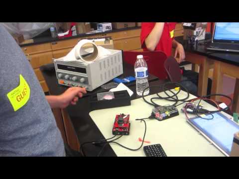
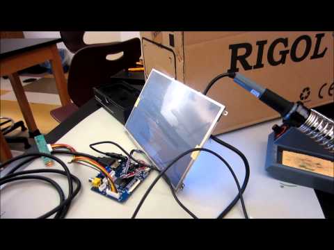
Here is a picture of my main case with a description:

Here is a picture of my remote with a description:

More pictures (for main case and remote): https://plus.google.com/photos/101733381104076420032/albums/5906426964440732929?authkey=CMCg9bW9tN2l_AE
Joystick Shield:
The actual joystick
There are two potentiometers, one on the x axis and one on the y axis which are connected to the joystick. This allows for us to get a very precise reading of where the joystick is at. The x axis pot is connected to analog pin 0 and the y axis pot is connected to analog pin 1.
The select button is connected to digital pin 2
The buttons
the buttons are connected to digital pins 3,4,5,6
I also made a case for my controller here are the pdfs. I used autocad for the cavity and tinkercad for the hood.
Arduino Code:
With bluetooth
Without bluetooth: https://github.com/Jped/BlueberryPi/blob/master/Joystick_arcade.ino
Raspberry Pi code
pyserial:https://github.com/Jped/BlueberryPi/blob/master/serialarduino.py
my pong (did not use for final bc of glitches): https://github.com/Jped/BlueberryPi/blob/master/Pongv2_with_new_edits.py
pong with joystick (pong taken from here; I modified it to work with my remote): https://github.com/Jped/BlueberryPi/blob/master/pong_v1.3.p
Mechanical Drawings
HOOD
PDF OF HOOD : hood (it is 0.085 inches thick)
DWG OF THE HOOD: hood_dwg
CAVITY
PDF OF CAVITY : (it holds the redboard; a battery pack and a joystick shield)
TOP VIEW PDF:cavity
SIDE VIEW PDF: cavity2
DWG OF THE WHOLE THING: cavity_dwg
MAIN CASE
I cut mine 0.25 inches thick because we had nothing else available; but if I had a choice, I would have done something a bit bigger (0.5 inches) so there would be no problem of screws sticking out.
PDF OF MAIN CASE:
You may have to zoom in for some of the pieces, I have yet to figure out how to correctly make a pdf in autocad.
Top: topcase (may not fit exact; I had a little collum inside my case, adjust to your needs!)
Bottom:bottomcase
Smaller Side: (one has groove for usb ports for raspberry pi) leftsidecase ;sideright
Larger Side (one has hole for the lcd display wires; other has a hole for the power to the lcd): I got both of them into one pdf! Yay!: othersides
DWG OF MAIN CASE: https://docs.google.com/file/d/0B6sV6aZImzHsYW1oaVcwTk9nTmc/edit?usp=sharing
Here is a link to my BOM: https://docs.google.com/spreadsheet/ccc?key=0AqsV6aZImzHsdDJJc0FJX2xNZzhnbUZSQ0tET2lEZlE&usp=sharing
Here is my parents night presentation (I come out at around 4:56):
Milestones
Milestone 3;creating the Pong pygame game and then modifying it to work with the remote:
I don’t have a lot of experience with pygame, but I decided the best way to get into it was to jump right in and create my game. During the first few days, I was blasting through my games reaching all of my goals. Towards the third day; I started reaching a lot of bumps. My main mistake was that I did not really know all the little nooks and crannies of Pong. I thought it was really simple but apparently there are a lot of random little things that I missed. The ball is supposed to speed up in pong, that is something I overlooked. Another mistake was that in some ways the physics of my game did not make any sense; when the ball would come from an angle and would hit the middle it would just go straight instead of going at the inverse angle of how it hit. Slowly but surely, I was knocking away each of these problems. But eventually it turned out that I had a lot of random glitches where the ball would do things it was not supposed to. On top of that, my code had some lag, which I later realized was because of the way I moved the ball. I kept on trying to fix the code till the end of week four. Again, I made a executive decision, to put my game on hold and use someone else’s pre written one, so I could finish the project. I eventually went back to the game later to fix it up.
The next step for me was to modify the code that I am using to work with the arduino controller. As always, it was an easy concept but actually implementing it brought about a lot of annoying glitches. So I decided that I would have it really simple, the arduino will output a word (ie “up” or “down”) to serial and the Raspi will read that and use it as a condition for one of the paddles; if the Raspi received up it will make the left paddle move up, if it received “down” it will make the paddle move down. The problem was that even though the Raspi was receiving these commands they were returning false in the condition when they should have been true. After doing a lot of research and finding out that the book that I was using was full of mistakes, I decided to seek the help of my fellow coders on stackoverflow. One person said that it was probably because of the extra whitespace that the arduino outputs. I decided to follow his advice and add .rstrip() (this removes all the whitespace to the right of the word).
Another small problem that I encountered was that the code for the Raspi would only proceed if it receives an input from the arduino; this would case the code to hold up a lot. The solution to this was pretty simple; I just added an if statement that checked if there was anything waiting in the serial port, if there was I would take it if there was nothing there I would just proceed with the code.
Milestone 2, getting bluetooth/serial to work with the raspberry pi:
For my project, my remote is made with a Sparkfun red board, a joystick shield, and a bluetooth module. The remote communicates to the Raspi through bluetooth.
This step probably took much more time than I expected. On the arduino side it was fairly simple; I followed a tutorial on sparkfun’s website and adjusted to suit my needs . Most of the complicated code was taken care of by the Software serial library for arduino. All of the bluetooth protocols were taken care by the actual bluetooth module.
The bulk of the work had to be done on the raspberry pi. At first I had to download the bluetooth drivers for the Raspi; I used the bluez driver by simply typing a simple command into the lxterminal; Sudo apt-get install bluetooth bluez-utils blueman.
After I did that I right clicked on the newly created bluetooth icon on the bottom right of the start bar. Then I clicked on devices, connected to the name that I gave to the Arduino Remote. After it successfully connected I right clicked on it and connected it through Serial (sometimes it is under the SPP option, with a little VGA icon next to it).
This is where all of the problems started to occur. The Bluetooth icon said it was connected to the device and the module on the arduino also said it was connected. I therefore safely assumed that the connection was AOK. This assumption proved to be correct, however; I still had a lot of other problems to deal with. The first was getting the two devices to communicate. After doing some research I came to the conclusion that there has not been much work in this area. Most of the examples were based on getting them to communicate with a wired connection. This made it even harder to make sure I was doing everything correctly. I started out with using the same module as the wired connections; pyserial. At first I loaded a very simple sketch on the raspberry pi that I found and modified for my use. My python code would listen to the port that the bluetooth was connected to and print all of the inputs to a file. Pretty simple stuff. I also added many print statements to work as debuggers. At first the code did not work at all; I was totally lost. Then I found a tutorial with some really helpful info. After some back and forth with the creator of the blog, I decided to use minicom (described at the end of the blog post) to test and see if there was any communication between the two. After loading up minicom, and trying several tests, I realized that there was a connection and there was some communication. That narrowed the problem to one problem; why isn’t pyserial working? After a few days of basically staring at my raspberry pi waiting for something magical to happen, oddly it started to work. But, it only worked when you opened up minicom made sure there is a connection and then ran the python program. This method was nowhere close to reliable it would only work sometimes. At the end of week 2 I decided that I do not have more time to spend on this and that I had to move on, even if it meant that I would have to use a wired connection at the end of the day.
Milestone 1, getting the raspberry pi up and running:
The first step I took to setup the Rasppi was flash raspbian onto the 32gb sd card. I used win32 disk imager. Then I hooked up the screen to the HDMI port on the Raspberry pi, the usb module for the keyboard, and the usb module for wifi. Then I plugged in the Pi and allowed it to boot up. At the config screen I selected the option to allow for the SD card to be used for memory. Then I proceeded on, I typed in the command to get to the GUI (startx), and made sure everything was up and running. Everything was a ok at first, but later I realized that when I would press shit \ it would not produce a vertical pipe |, the vertical pipe is very essential in programming and also for downloading packages through the terminal. After looking around and asking some people on the forums, I concluded that I needed to change the keyboard layout configuration in the config menu from the beginning. To get there I needed to type in the command “sudo raspi-config” in the terminal. Once I got there I changed the keyboard layout to English (US) and I chose the option for the “Generic Keyboard 104”. After the raspberry pi rebooted it worked!
Starter Project:
Here is a little summary of the starter project I made, the times square watch, enjoy!:
For my starter project, I built a timesquare watch, this watch is a stylish DIY watch kit made by adafruit. The display of this watch is a led matrix. Time could be displayed in either a marquee mode or a binary mode. The watch also has a moon phase mode and a mode that shows how much battery power is left.
The circuit design for this watch had to use the least amount of power so it could last for more than a few days. Therefore, Ladylala and the adafruit team had to be careful and selective in what parts are used, and how the code was written. The watch runs on a CR2032 Coin cell battery. The CR2032 is a thin 3.0v lithium ion button battery. This battery outputs about 200 mAh of current.
At the heart of this watch is an Atmega328P. This microcontroller is very similar to the one used in an arduino. The arduino uses the Atmega328; the 328p is a low power version of the 328. The microcontroller receives the time from the DS1337 timer chip and displays it on to the led matrix.
The DS1337 is a time chip that used I2C to ‘talk’ to the microcontroller. I2C is a method that allows a slave (the timer chip) to talk to a master (the microcontroller) only using two I/O (input, output) pins. This allows for more I/O on the microcontroller to be free to use. The timer chip uses a crystal oscillator to keep track of the time. The oscillator gives out a pulse and the timer uses that pulse to keep track of the time. This oscillator with the timer chip is used in many watches and other devices that need to keep track of time. The reason why these crystals are so popular is because they are small and very accurate.
There are several 47 ohm resistors that are used when the microcontroller connects to the leds in the matrix so that they do not burn. A led matrix is a whole lot of leds put into one compact component. This technology is used for led tvs, but on a much larger scale with much smaller leds.
There are also two buttons that are inputs to the microcontroller. When pressed they close a circut and allow for electricity to move through, the microcontroller senses this and as a result the microcontroller processes code that switches to another mode.
Additionally, there is a 10k resistor and a 0.1 microfarad capacitor,they are used when a FTDI chip is connected. The FTDI chip allows for the watch to be reprogrammed with a computer.
Reflections
Overall I think I have learned a few very important facts here at bluestamp. I learned that nothing is out of my reach. If I want to build something most of the time I am able to do it, I just need to focus and be inspired. I learned that the hard part is usually not building or creating the device or program, it is thinking of it.
Another, important reality that I have learned is that most of the time spent on a project is debugging it. Although this sucks, it is the inconvenient truth (no not the Al Gore movie).
I also learned that it is very important to have relationships with other people, because it will more than likely help you in the future.