Mini Sumo Robot
The Mini Sumo Robot allows you to have many hours of fun. You can crash into other people’s robots. The Mini Sumo Robot is a robot, hence the name, that “wrestles” other robots by crashing into them and pushing them back to make your robot look like the stronger one.
Engineer
Jonathan W.
Area of Interest
Mechanical/Electrical Engineering
School
Westmoor High School
Grade
Incoming Senior
Showcase Night Presentation
Final Milestone
My final milestone is assembling the shell of the mini sumo robot and integrating the electronic parts.The main body, or chassis, is used to hold two motors, the Arduino Uno and the rest of the electronics. The motors are attached to its own wheel, but there was one problem. This problem was that the wheel wasn’t really gripping onto the motor, so the solution I came up with was to use hot glue. It worked for about five to ten seconds, but then the wheel would become loose. So to fix this problem I changed the use of hot glue to super glue. There were other problems with the other wheels themselves. They had too much friction to spin, so I filed the center and made it more frictionless making the wheels free to spin. Next, the wheels were attached to each other on one side (3 on one side, one motor on one side) with a drive belt. To put the wheels onto the chassis I used axles and retention rings. The axles are used to hold the wheels in place and the retention rings are used to hold the wheels in place onto the axle. However, the belts caused too much friction making the wheels not turn, therefore I took them off and I didn’t replace it with anything since only one wheel had to spin on either side for the entire machine to move. Next for the friction on a table or the floor, I used some neoprene rubber as its tire. Using the neoprene rubber makes it have more friction on the table or floor making it easier to rotate and move. Another challenge is fitting everything into the small chassis. The chassis is like a box, where you have to fit everything in it, but the wires are sticking out and I can’t put the cover on it. One thing I can do is shorten the wires, however I did try that but the wires will not reach the breadboard and arduino uno.The last thing to put into the robot are the ultrasonic sensors. I had to file the ramp so that the ultrasonic sensors could fit into it and I hot glued the ramp onto the chassis.
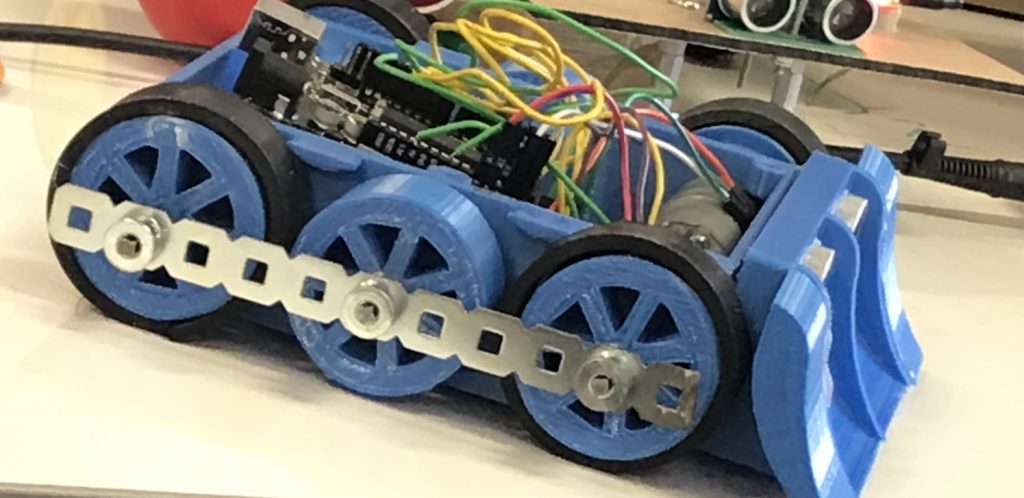
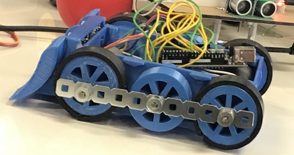
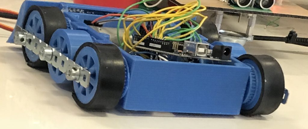
Final product from most angles
Section 1
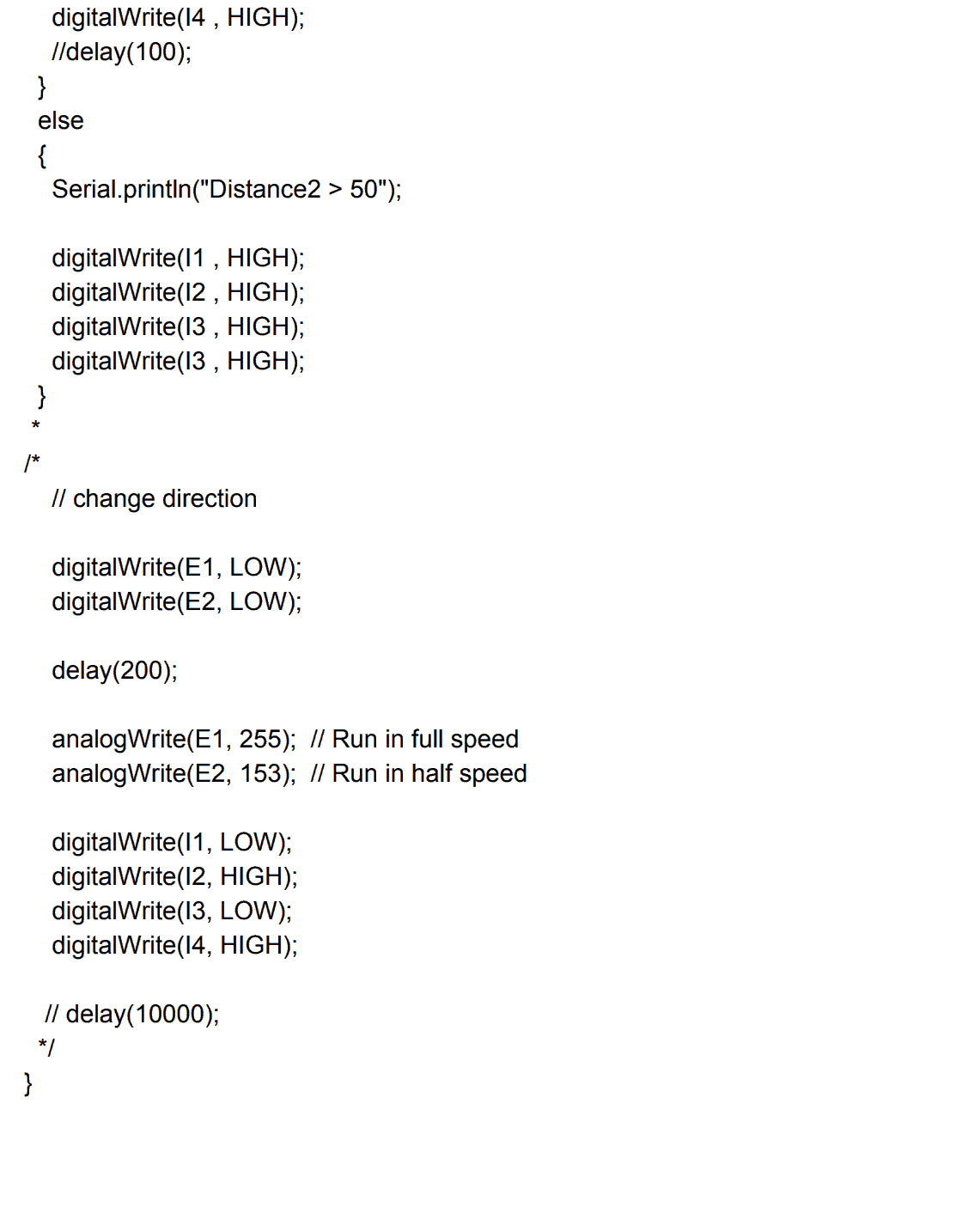
Code 1
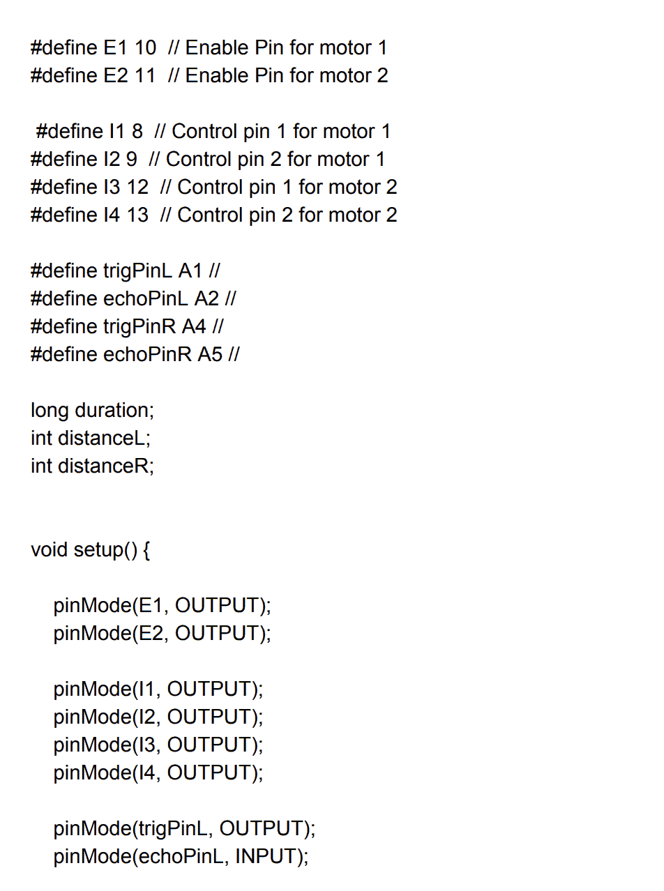
Code 2
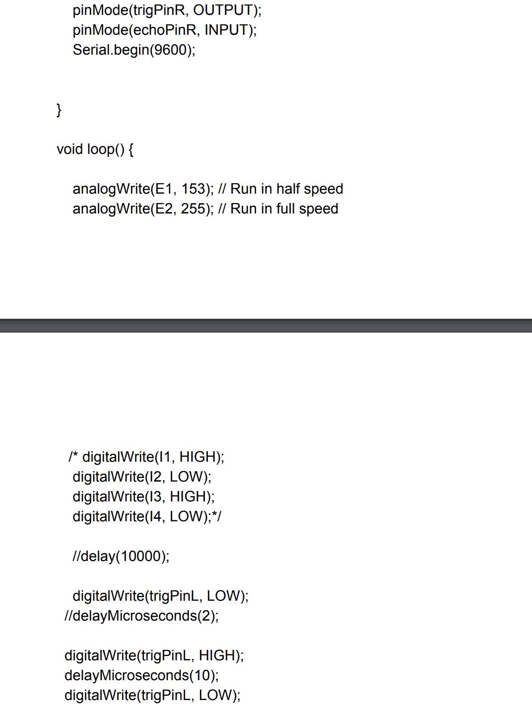
Code 3
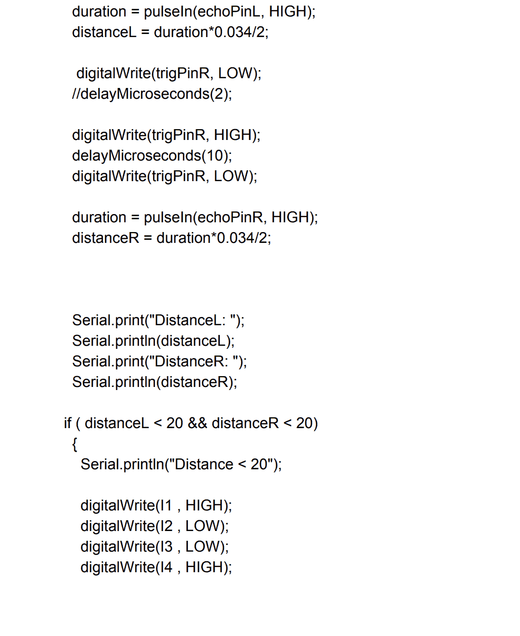
Code 4
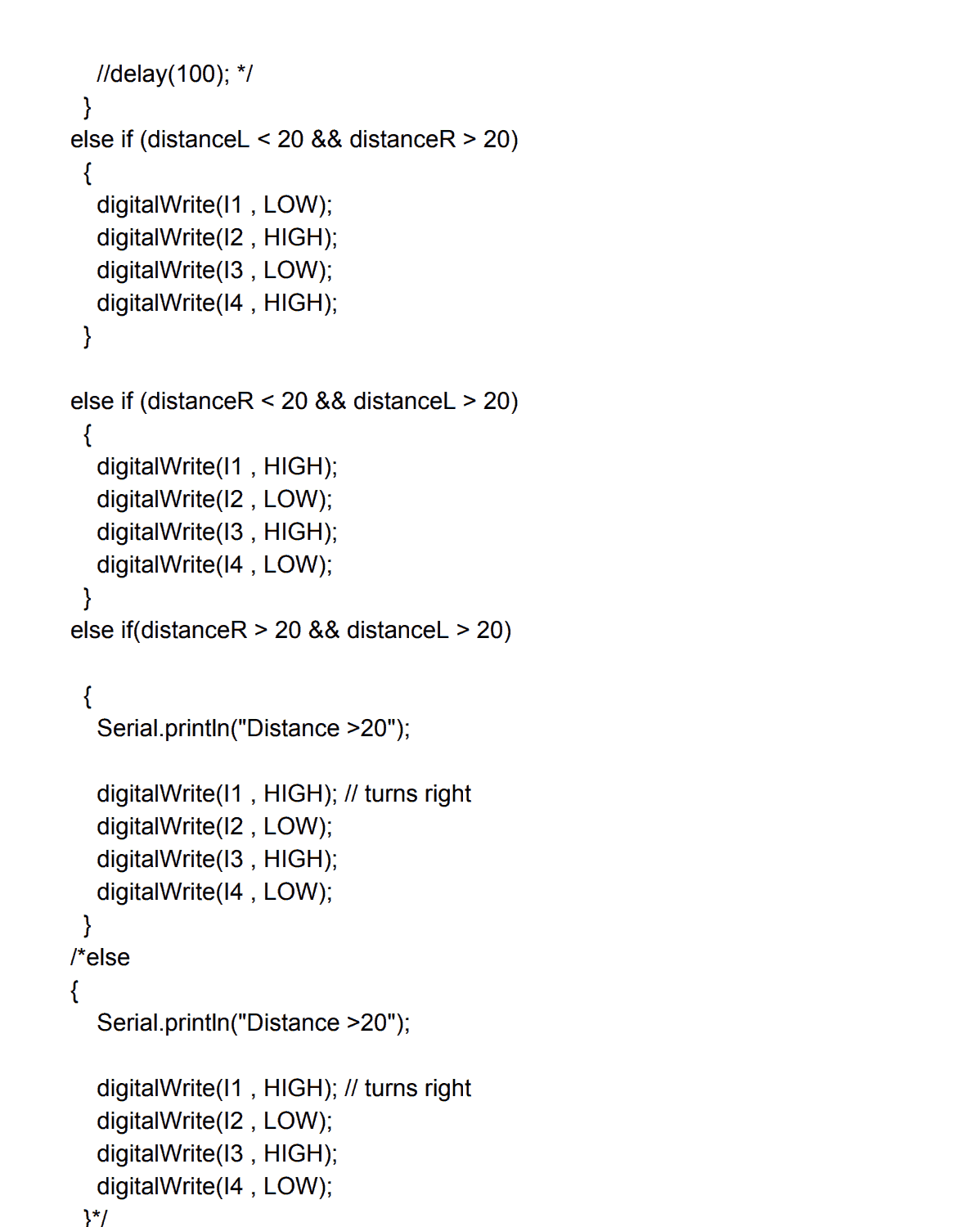
Code 5
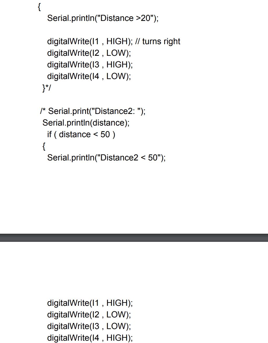
Code 6
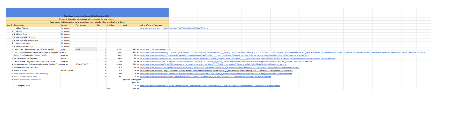
Build of Materials
Second Milestone
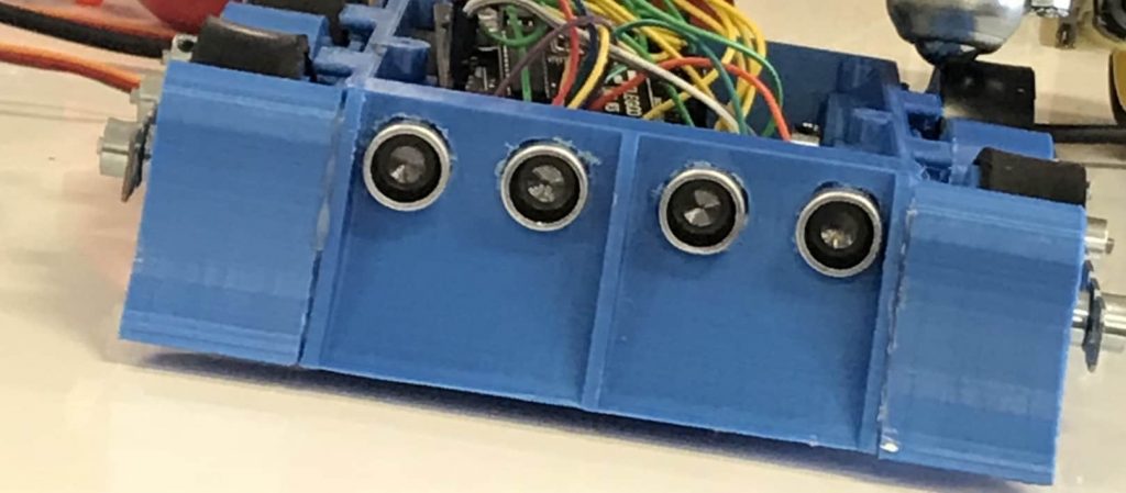
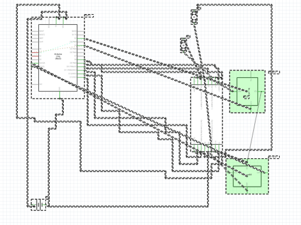
My second milestone is me getting the motors to be controlled to go forward or backwards depending on the distance from the ultrasonic sensors. The ultrasonic sensors are the HC-SR04. The Ultrasonic Sensors uses sonar-like transmission (like bats and dolphins.. Etc) in order to calculate the distance of an object. It consists of an ultrasonic transmitter, receiver and control circuit. The transmitter transmits short bursts which gets reflected by target and are picked up by the receiver. The time difference between transmission and reception of ultrasonic signals is calculated. Using the speed of sound and ‘Speed = Distance/Time’ equation, the distance between the source and target can be easily calculated.Time taken by pulse is actually for to and from travel of ultrasonic signals, while we need only half of this. Therefore time is taken as time/2. Distance = Speed * Time/2. Speed of sound at sea level = 343 m/s or 34300 cm/s. Thus, Distance = 17150 * Time (unit cm). This sensor has 4 pins: a Vcc, a Trig, a Echo, and finally a Gnd. The Vcc pin powers the sensor, typically with +5V. Trigger pin is an Input pin. This pin has to be kept high for 10μs to initialize measurement by sending Ultrasonic wave. Echo pin is an Output pin. This pin goes high for a period of time which will be equal to the time taken for the UltraSonic wave to return back to the sensor. The Gnd pin, this pin is connected to the Ground of the system. When something is less than 20 cm away it will go forward and push in that direction and not back down to anyone. When it is more than 20 cm away the robot with move backwards until it finds something in the less than 20 cm away mark. They are both powered by the 5V pin from the Arduino Uno. They are telling the motors to go forward and push once the distance between the object and itself becomes low enough. When one sensor senses something, it will turn in the direction of the object and center itself. The challenge itself was getting the motors to do exactly what I want it to do. The coding for the motors were quite difficult since I have little to no experience coding. I had to code it so that it will turn in the direction of the object and center itself so it can go forward and push forward. The first challenge that I had was that my motors were jittering due to my code being wrong and oversimplified. Instead of declaring both sensors, I only declared one of them making the motors stall. The second challenge I faced was the getting both sensors to work at the same time using code that was written wrong as mentioned in the first challenge.
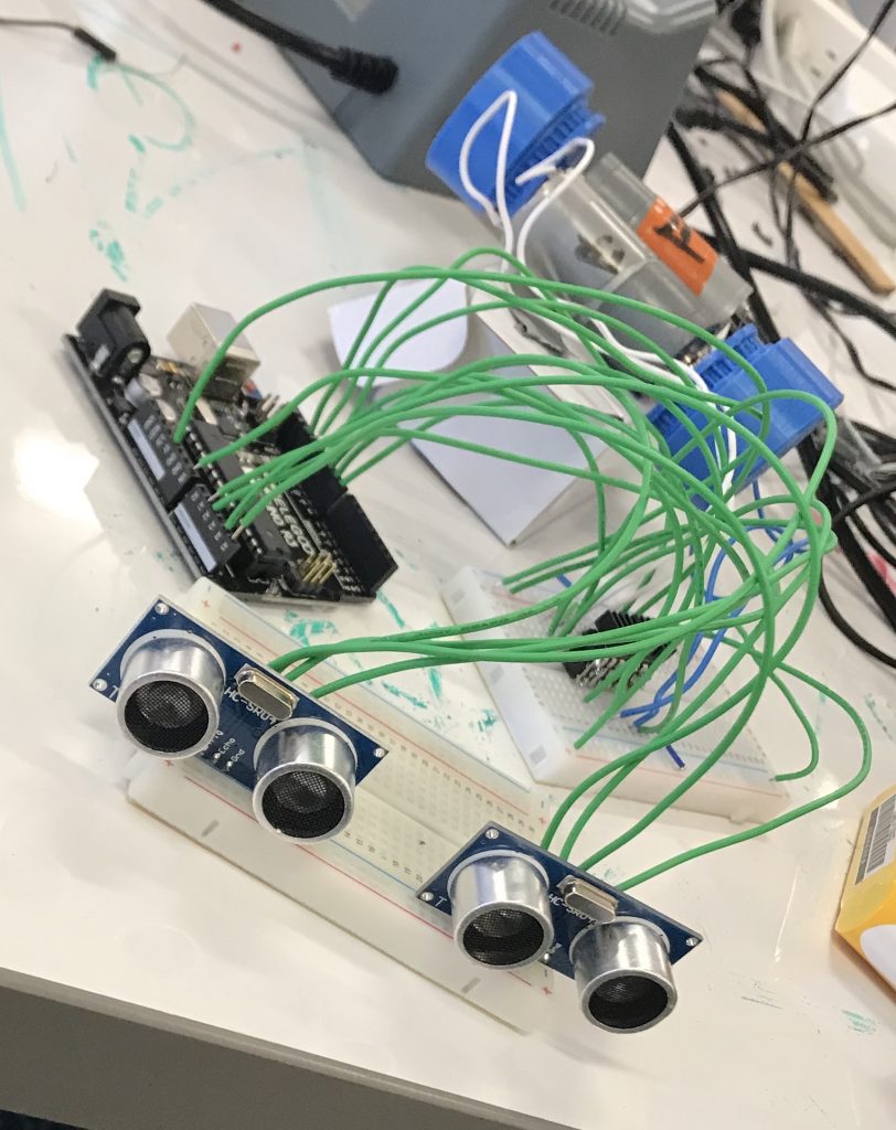
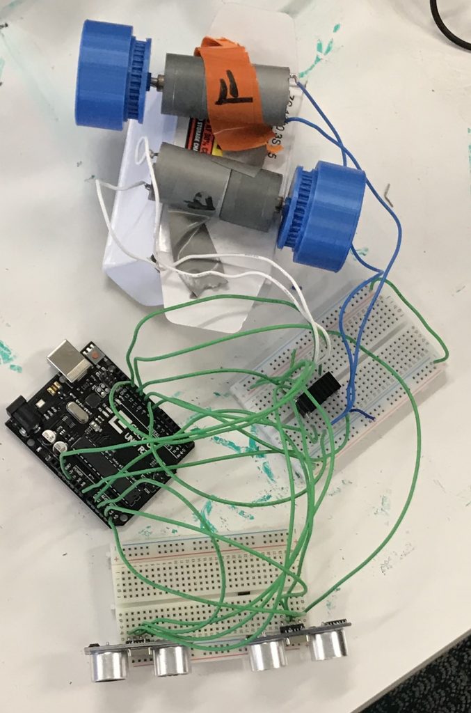
The motors with the h-bridge and ultrasonic sensors
First Milestone
My first milestone is making both of the motors move simultaneously using arduino code. After about 10 seconds, it will change directions from forward to backwards. It is being controlled by an arduino uno and 3 H-bridges with a heatsink so it doesn’t overheat.
An H-bridge is an electronic circuit that enables a voltage to be applied across a load in opposite direction. These circuits are often used in robotics and other applications to allow DC motors to run forwards or backwards. The H-bridge arrangement is generally used to reverse the polarity/direction of the motor, but can also be used to ‘brake’ the motor, where the motor comes to a sudden stop, as the motor’s terminals are shorted, or to let the motor ‘free run’ to a stop, as the motor is effectively disconnected from the circuit.
The type of motors I used are DC motors. A DC motor is any of a class of rotary electrical machines that converts direct current electrical energy into mechanical energy. The most common types rely on the forces produced by magnetic fields. Nearly all types of DC motors have some internal mechanism, either electromechanical or electronic, to periodically change the direction of current flow in part of the motor.
I used an Arduino Uno for coding my motors for it to move. The Arduino Uno is a microcontroller that is used to control the H-bridge. The Uno has a 5V pin that is used to power the H-bridge itself and takes in 11.1V from the VIN pin and converts it to 5V using its voltage regulator.
The challenges that I have faced in this first milestone are actually the motor controller and microcontroller themselves. I had to switch out my microcontroller from the nano to the uno and also take my motor controller and switch it out with three h-bridges. This way it was a lot more simple and easier to work with. However it was still difficult because when I used only one h-bridge, it would overheat, so it couldn’t move the motors for a long period of time. The three h-bridges allowed them to not overheat as much as before so, it can be used for a longer period of time. The longer period of time allows the sumo robot to be able to ‘fight’ for a longer period of time by pushing the other one longer hence the name mini sumo robot.
My next step is going to be me putting in ultrasonic sensors to control when the motors will stop.
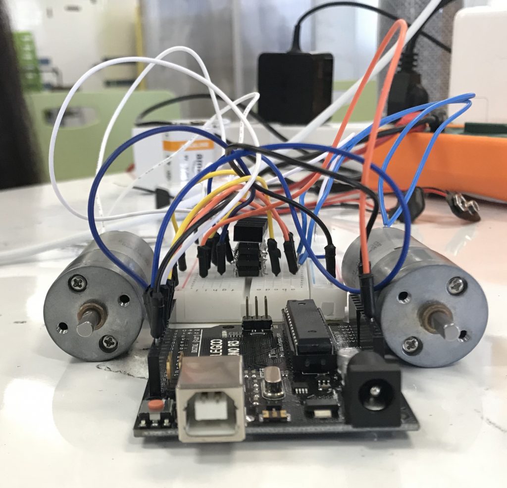
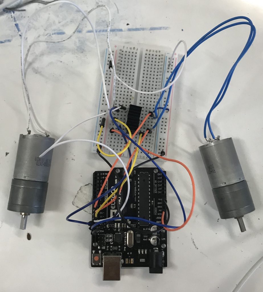
Just the motors with the arduino
Starter Project- Mintyboost
My Starter Project is the Mintyboost project. This allowed me to learn the basics of soldering and also to learn the basics of all equipment available. Upon learning the uses of the equipment, I also learned about circuitry and everything that has to deal with it.
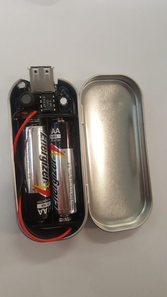
The Mintyboost is a device that charges your electronic devices that have a usb charger. This device is portable and can be placed into your pocket which is perfect for any place and time. The only downside is that you need to have fresh AA batteries at your disposal.The device uses two AA batteries to charge your electronic device!
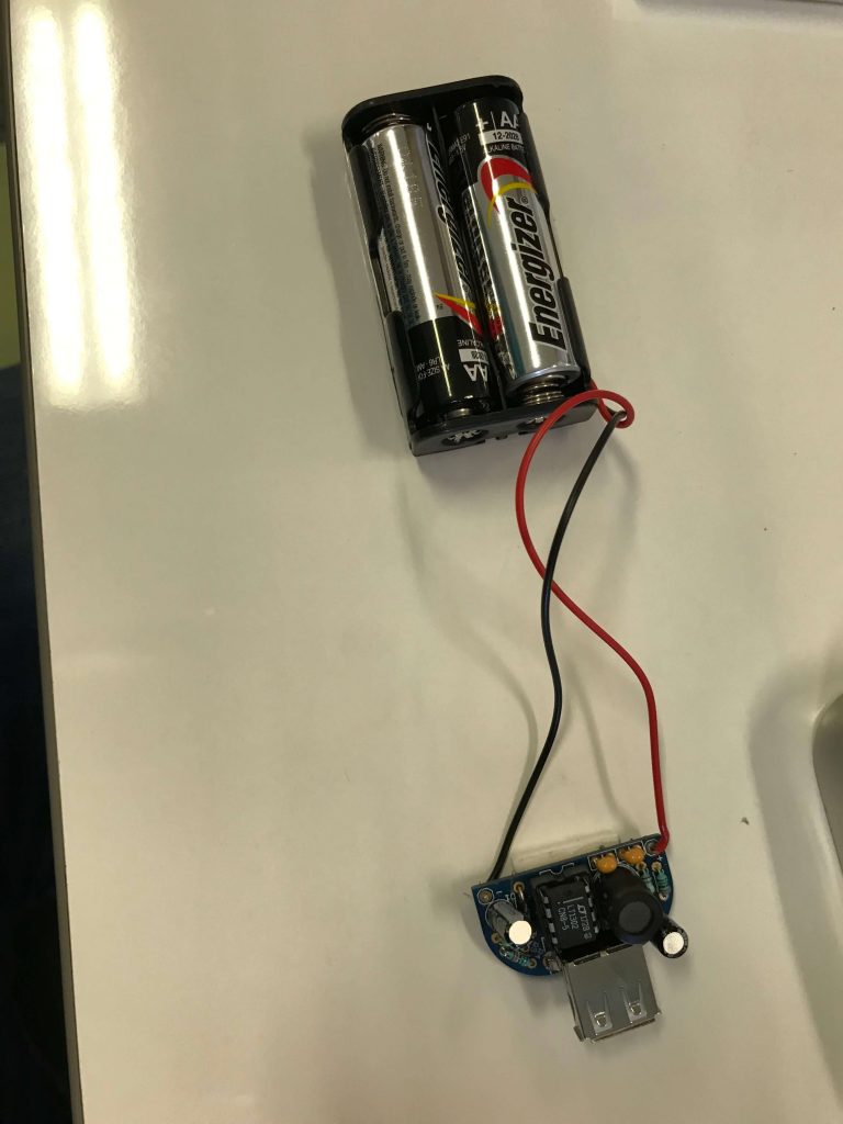
The power source of the device are 2-AA batteries. The mintyboost is a voltage source which means it maintains a 5 volt output no matter what the current draw (by the target device) is, which is why we have the 5V boost converter. The 2-AA batteries have a total voltage of 3V, each having 1.5V. The 5V boost converter boosts these batteries as the name mentions. Next are the four resistors. The four resistors create a voltage at each of the data lines that’s not 3.3V but rather 2.8 and 2.0 (or so) volts. This is perfect for Apple devices. There are two resistors with resistances of 75K Ohms and the other two of 49.9K Ohms. These resistances allow the device to not overheat by lowering the amount of current traveling through the wire. Next is the capacitor. This capacitor is used to stabilize the internal reference of the boost converter chip. This keeps the chip stable so that it will generate a voltage as precise as possible. Next is the IC socket. This protects the chip and allows you to replace it if there are any problems. The socket goes over the 3.3K resistor but the resistor should not interfere. Then there is the Schottky Diode. A Schottky diode, also known as a hot carrier diode, is a semiconductor diode which has a low forward voltage drop and a very fast switching action. There is a small voltage drop across the diode terminals when current flows through a diode. Then, there is a power inductor of 10 microHenrys. Power inductors are also used in order to store energy, provide lower signal loss in system design and filter EMI noise. Next are the two electrolytic capacitors. These help smooth both the input and output voltages, to keep them stable during the up-conversion. Finally, there is the usb type a connector. This is used to connect your usb in order for you to charge.
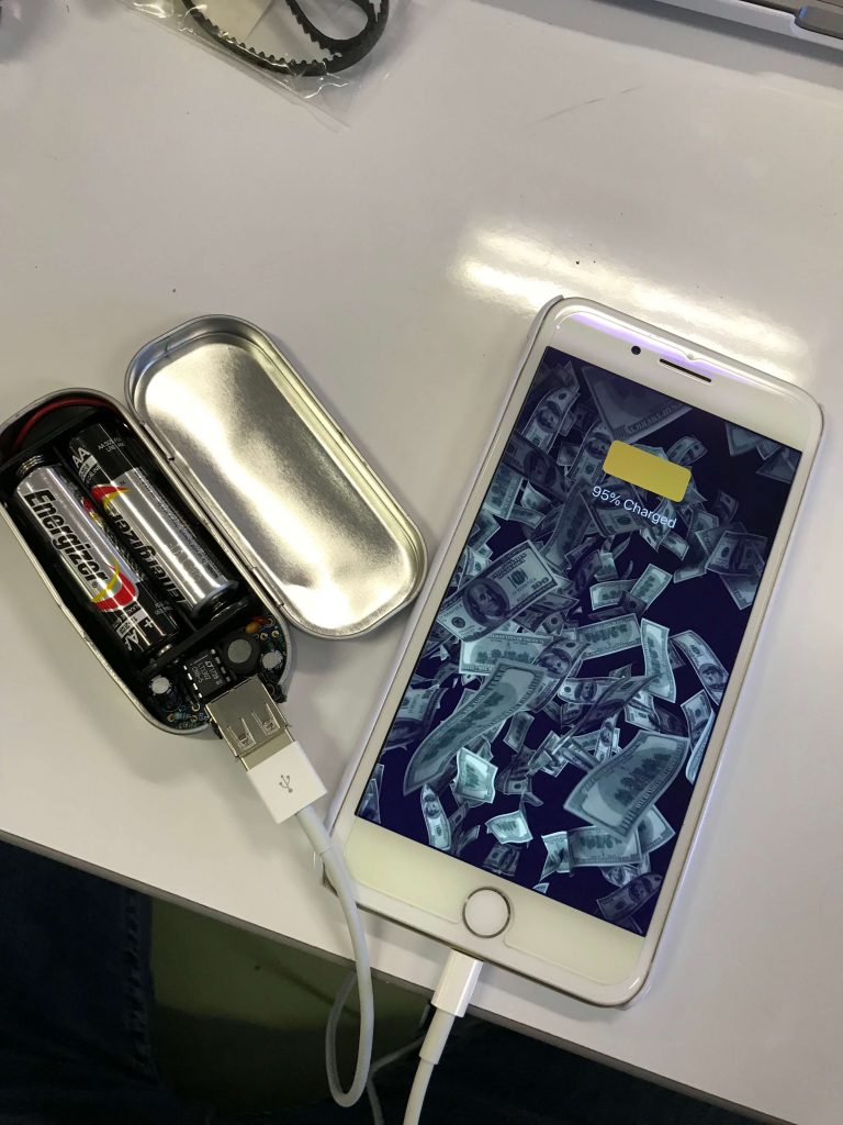
Minty boost it charges the phone!!!
Works Cited
“Controlling Speed of DC Motors Using Arduino.” Hardware Fun, 18 May 2015, hardwarefun.com/tutorials/controlling-speed-of-dc-motors-using-arduino.