
Hi my name is JohnLuke. I am a rising junior at Archbishop Molloy HS. For my starter project at BlueStamp Engineering I chose the Minty Boost, a 3V to 5V boost converter phone charger. For my main project I am going to design an LED binary clock and hope to add modifications such as the adding weather to display and a power switch to turn it on and off as necessary. At Blue Stamp I never was expecting a learning/teaching style such as theirs. It taught the principle of self perseverance and also leaned how to code and not get discouraged when I don’t know something completely. I liked Blue Stamp so much I am currently in the process of getting a similar program incorporated into my school. Being a 6 week student definitely taught so much and I would love to come back next year and make something even more impressive.
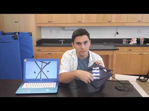
Final
My code has 2 functions:
- DECtoBIN
- LightUp
The DECtoBIN function takes the time given from the Ds3231 real time clock and converts it into Binary. I do this by using modulo and setting the remainder always equal to 0.Then since each section for the hours minutes and seconds has eight neopixels I also programmed it to add enough 0’s to make it 8 digits long. 32 in BIN is 10000 and is read right to left. By adding two 0’s to the left will not change the number itself but make it so the number is now 8 digits long. Then Light up searches for the 1’s(lit up) and the 0’s(not lit up) and tells the neo pixels accordingly where and how to light up. I had the Adafruit neo pixel master library, the wire library, and the library for the DS 3231 rtc. How the clock itself works is neo pixels 7-3, 15-11, and 19-23 going from highest number to lowest to number represent 1,2,4,8,16. Neo pixels 10 and 18 represent 32. Alot of addition goes into figuring out how to tell the time on this clock. If the neopixel is lit it means it has to be added to another lit neo pixel for it group to tell the time. So if the neo pixel representing 16 and 1 is lit up in the minute columns then the minute is 17 because 1+16=17. This link will take to you to where I got inspiration for my project. As you can see my clock is very different in 2 ways. I used the neo pixels instaed of LEDs and used wood to make my clock. I hand cut each piece and also 3D printed the support to hold the panels up and also store the Arduino under. The DS3231 takes scl to A4 and sda to A5 on the Arduino. The neo pixels strips go to pin 6. I used a pcb to supply power to all the components.


I didnt want to follow the instructables because I wanted to make my own clock. I had never coded anything before and this project at Blue Stamp Engineering has really given alot more confidence in my coding capabilities.
Second Milestone
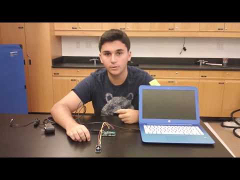
For my second milestone I programmed the time and the temp in Celcius using the ds3231 real time clock.
In this code there is also my DectoBin Function which was not in my milestone video. What that function does is convert the DEC values from the ds3231 and coverts them to binary . I used “while”to do this. I made my variable “rn” and made it blank.
I also made the pieces for the frames of clock. You will need to cut 2 10 inch by 10 inch squares. 1 square will be left to be the back of the clock and the other you will proceed to cut as follows. You will need to cut both vertically and horizontally through the middle so you will have 4 triangles. Then for all four you cut from the top angle of the triangle to the middle of the base and get something like this.


First Milesone
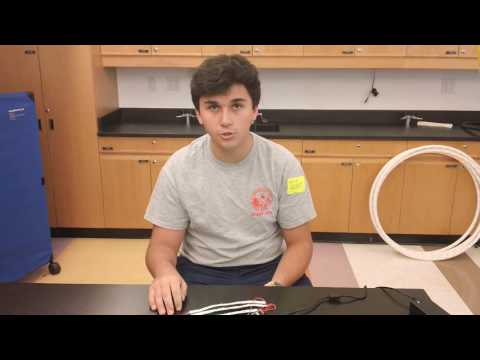
For my first milestone I programmed my neopixels to go in a chase across the 4 strips. I programmed 5 colors that can represent the raibow.
Doing this only benefited my project by me learning the neopixel library and coding something for the first time. How the code works is I put the function “chase” then set the color in RGB format. RGB stands for red, green, blue. The chase function sends a line of colors through the 24 neopixels I set up together. I put comments with my static void to show to use of that. What it does is erase the neopixels once there have been 4 lit up.
Starter Project

Power from within the Minty Boost the flows from the 3V battery pack to a capacitor which stabilizes the flow of energy. From there it goes to the power inductor. The power inductor and the IC chip work together in order to reach 5V. In order to do this the IC chip flips a switch, causing the loss of some electrical energy. The inductor opposes this change by converting some of its magnetic energy into electrical energy. Once it reaches 5V the IC chip senses this and allows the current to flow through the diode and the USB port to charge your phone.

Keep up the good work. Its impressive to see how you can design, create and build these electrical and mechanical devices in such in short time in this class.
Great job Johnluke! It is really amazing how you converted time into binary. You explained really well.