Jessica S.
Hi, my name is Jessica and I am a rising senior at the Bronx High School of Science. I am a veteran of the Construction department of the SciBorgs Robotics Team and I am a part of the Varsity Badminton Team. My starter project is the MintySynth Kit 2.0 and my main project is the knee activity monitor with bluetooth. The MintySynth is an Arduino-compatible synthesizer that fits in a mint box. It uses a microcontroller that is preloaded with the MintySynth software which uses oscillating signals and waveforms to produce sound. I chose the MintySynth as my starter project because I love music. It was also an opportunity to learn a lot about electronics, and circuits; areas of engineering that I didn’t come into contact with before this program. The knee activity monitor is a knee sleeve that monitors the user’s biomechanics while they are performing a certain exercise. It measures the angle and angular velocity of the knee during exercise. Particularly, it tells users whether or not they are doing their rehabilitation exercises properly without a physical therapist present. I chose this project because of my interests in biomedical engineering. This project encompasses many aspects of engineering, like coding and electrical engineering, which are all fundamentally important as a biomedical engineer.
Engineer
Jessica
Area of Interest
Biomedical Engineering
School
The Bronx High School of Science
Grade
Incoming Senior
Final Milestone
My main project is a knee activity monitor. It is a sleeve that measures the angle that a knee is bending at. This is designed to help people monitor their biomechanics and allow patients to efficiently do certain rehab exercises, like squats, at home without the supervision of a physical therapist. It allows an average person to monitor their biomechanics.
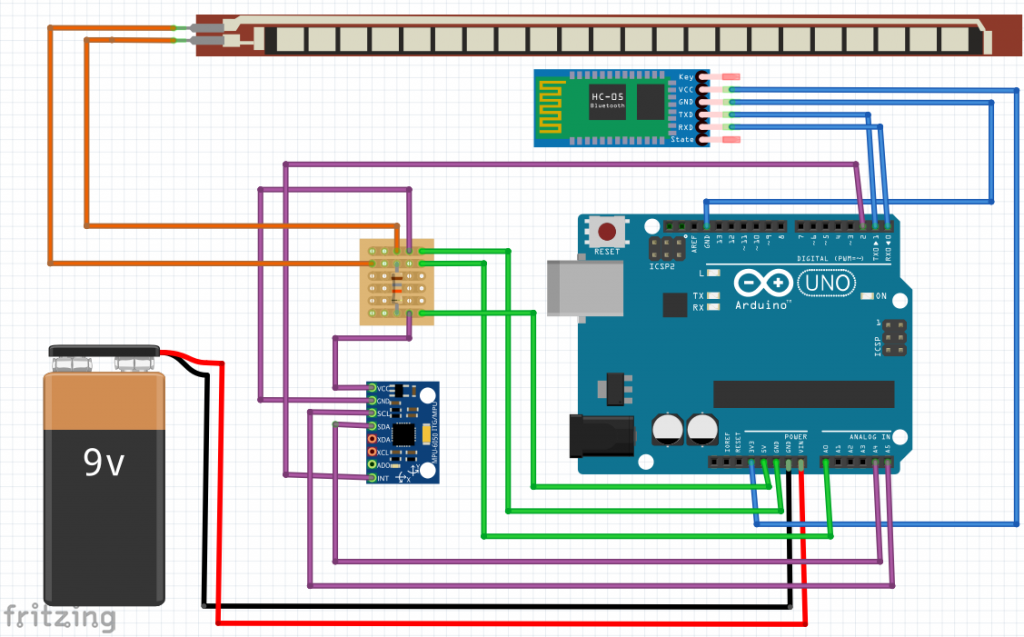
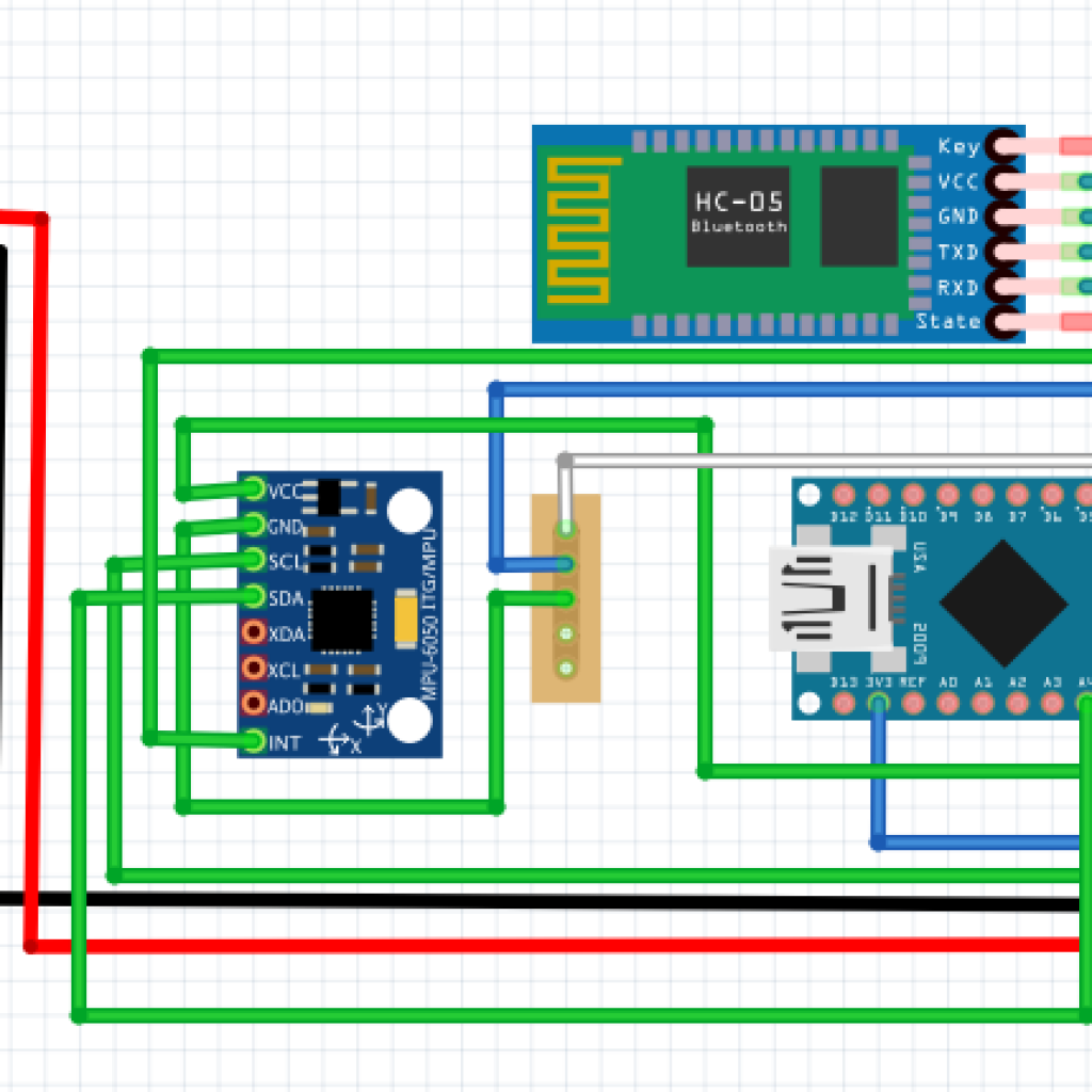
On the knee sleeve, the angle can be measured in two ways. There is a bend sensor that I made using neoprene and conductive fabric. It was created by using neoprene which is the exterior, and velostat, which is in between two pieces of neoprene. Velostat is a conductive fabric that allows resistance to build up. The neoprene and velostat were sewn together using conductive thread. At the ends of the neoprene, there is conductive fabric, where the jumper wires were sewn into. The sensor reacts to decreases in resistance which is caused by bending the sensor. There is also an accelerometer which has a gyroscope in it. The data from the accelerometer can be displayed graphically through Processing. On the wrist sleeve, there is only one method of measuring the angle. I only used an accelerometer, which is a small chip and is more accurate for measuring the bend angle.
From the second milestone, I’ve made several modifications. I originally used an arduino pro mini with a 9V to 5V voltage regulator and then a voltage divider to convert 5V to 3.3V. Instead, I am now using an arduino nano. Although it is slightly larger than the pro mini, it has a 3.3V pin and is able to convert 9V to 5V so I can eliminate the voltage regulating circuit completely. Also, I was going to add a wifi module to my project in order to communicate wirelessly. However, at Ramaz, the wifi network has a captive portal. This requires you to sign in after connecting to the open network which prevents the wifi module from connecting to it. Thus, in order to make the sleeve wireless, I decided to go with a bluetooth module which connects to my laptop and can display the graph in Processing.
My greatest challenge for this project was the wireless communication. I initially wanted to add a wifi module to the sleeves so that the sleeve could send data to a website and the graphical display could be seen by anyone with the website. I had to learn about how wifi works and how I would theoretically send data from the arduino to a server and then to a website. I worked on the several different codes to try to connect the wifi module to the wifi and being able to communicate and configure it from my laptop. However, the captive portal in the Ramaz Wifi preventing me from being able to test out the code and ultimately using that module.
My next step is to be able to display the graph of the data from the accelerometer on either a website or an app. It doesn’t require users to have Processing installed and would ultimately make this sleeve more accessible and easier to use for an average patient.
Documentation:
Project BOM:
Arduino Bend Sensor Code:
Accelerometer MPU6050 Code:
Knee Sleeve Circuit Fritzing Diagram
Wrist Sleeve Circuit Fritzing
Reflection
These six weeks flew by so quickly! I came into this program with a bit of trepidation. I loved the idea of making my own “medical device” and being able to explore so many different kinds of engineering this summer. However, I knew that as soon as I touched upon the coding aspect of the project, I would have to work very hard to not only understand the coding language but also how to create my own code to fit my needs. Six weeks later, I have a working wireless knee and wrist sleeve and I’ve learned that as long as I put my mind to it, as long as I work hard towards a goal, anything is possible.
From this program, one of the most important things I learned was self-learning and problem solving. I came into the program with no experience in coding and electrical engineering. The only engineering experience I did have was being on the construction department of the robotics team. During these 6 weeks, I’ve had to code, create and plan circuits and learn about wireless communication. These are all topics that I probably wouldn’t have even touched upon without the motivation of completing my main project. As I was putting together all of the code, I experienced a lot of challenges. Often, the instructors didn’t know exactly what was causing all of the errors. I had to look up each and every function to understand the syntax and what it did and why it was causing an error. I would revisit my code multiple times a day just to figure out what was wrong. Sometimes it would take days before I figured out what was wrong and how to fix it. But at the end of the day, this program gave me a lot of motivation to explore different fields of engineering with lots of hands on experience. I learned that biomedical engineering is the best field for me because I enjoyed all aspects of my project, from the electrical engineering circuitry side to the computer programming side, and brainstorming how this device could be the next innovation in the medical industry.